


This video describes what the “phase dots” are that you often see adjacent to windings of a transformer. It discusses how these dots are used in certain circuits to establish a desired phase relationship between the signals on the various windings. A couple of tips are given regarding how to determine the phasing relationship on homebrew transformers. Finally, measurements are made with an oscilloscope on a trifilar wound transformer to see the phase relationship between the signals on each of the windings with respect to the phasing dots.
Basics of Phase Dots on Transformer Windings – [Link]
RELATED POSTS
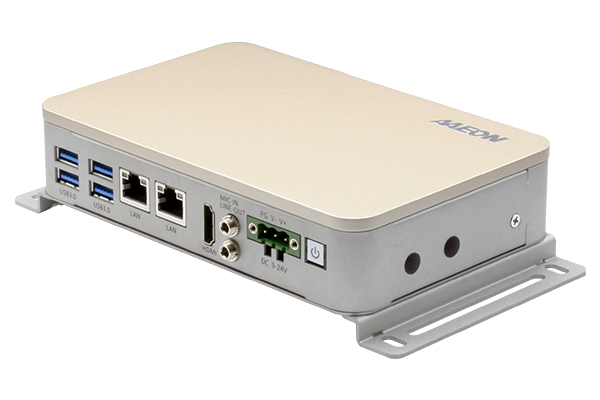 25 September, 2019 The BOXER-8300AI Series: Powering AI@Edge with Intel® Movidius™ Myriad™ X
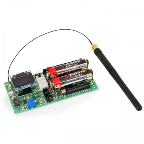 8 October, 2018 ANTENNINO – Arduino-RF multifunction board
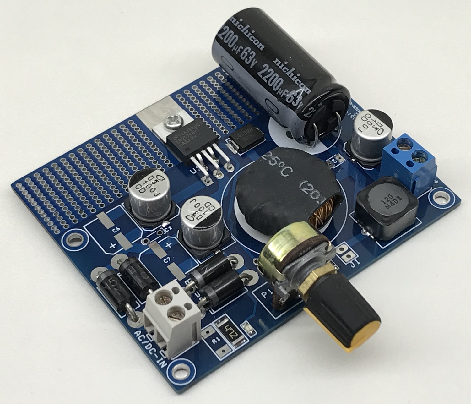 2 April, 2021 1.2V to 50V @ 3A – Adjustable Power Supply with 55Vdc Input
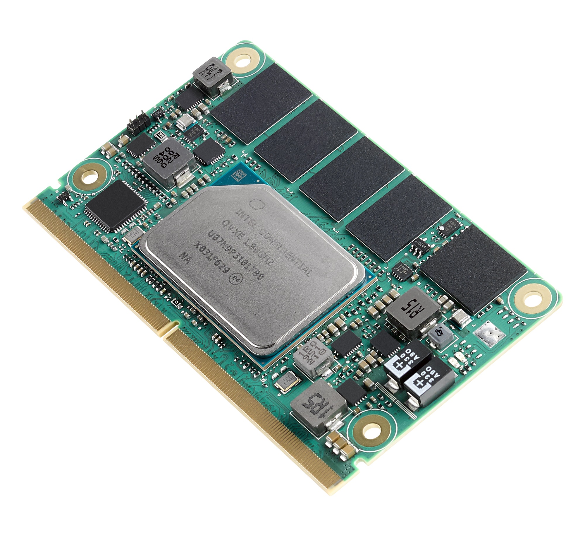 27 October, 2020 Advantech Launches Latest SMARC 2.1 Design SOM-2532 for Real Time Automation Control
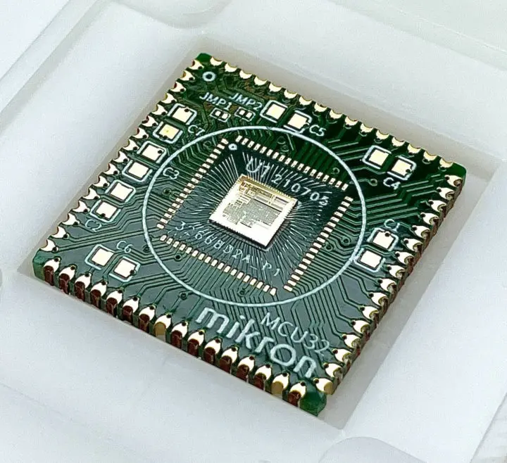 20 September, 2021 Russian Company Develops A Mikron Mik32 MCU With Features Similar To STM32l0 MCU
 17 March, 2020 Gumstix Supports Raspberry Pi Makers
Subscribe
Login
0 Comments


