


In this tutorial, you’ll learn how to burn Arduino bootloader on a new ATmega328 using USBasp ISP programmer. Every Arduino Uno Board comes with a microcontroller called the Atemga328P, and they are already pre-program with Arduino Bootloader firmware. Therefore, there is no need to burn Arduino bootloader into those Atmega328P chips again. Here, we will be focusing on burning the Arduino bootloader on an off the shelf Atmega328 chip so that you could make your own DIY Arduino board or deploy your Arduino-based circuit to a printed circuit board.
Required components:
- USBasp Programmer
- AVRdude Software
- Breadboard
- ATmega328P
- 2pcs 22pf Cap
- 16MHz Crystal
- 10K Resistor
- Hook up wires
First of all wire up the circuit in the breadboard as shown in the diagram above. Please connect all the connections carefully.
In above circuit JP1 is where USBasp programmer is connected. Connect all the wires carefully as per above diagram using a jumper wire.
Software Install
If you wire up your circuit correctly then it’s time to load hex file which is located in your Arduino software folder. Here is the complete path for Arduino 1.x in windows – C:\Program Files (x86)\Arduino\hardware\arduino\avr\bootloaders\optiboot\optiboot_atmega328.hex you can also download from here optiboot_atmega328
Next, you need to install AVRdude software and USBasp Programmer Driver.
Bootloading
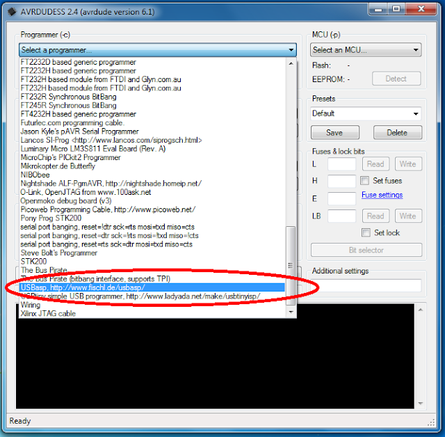
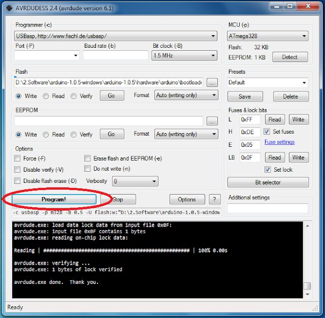
Open the AVRdude software and select programmer type from the drop-down list shown in below image. In our case programmer is the USBasp programmer.
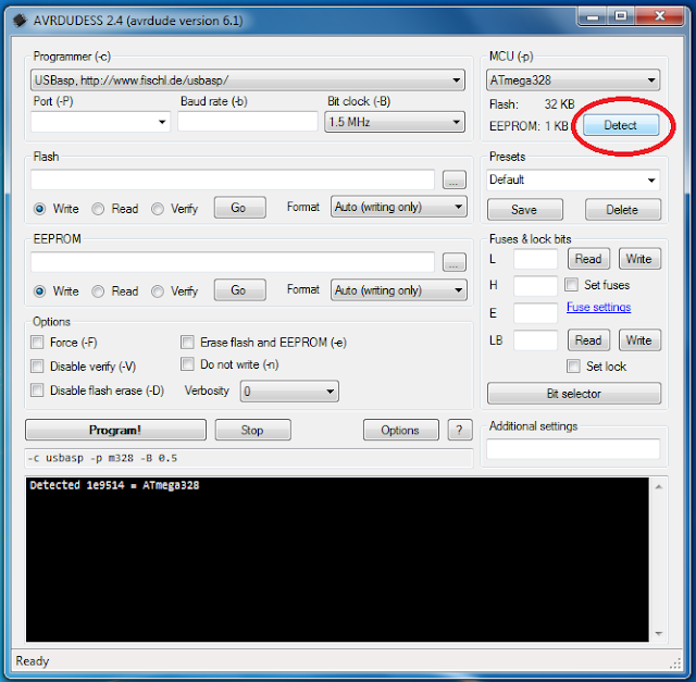
After Selecting programmer type click on “Detect” so programmer automatically detects ATmega328. If you have any problem with detecting microcontroller check all connections carefully.
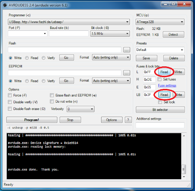
After detecting microcontroller, it’s time to read fuse bits and lock bits. As shown in below screenshot click on “Read.”
The default value of fuse bit.
- LOW Fuse : 0x62
- HIGH Fuse : 0xD9
- Extended : 0x07
- LOCK :0xFF
To configure the Atmega328 for use with Arduino Uno boards, set the fuse settings as below:
- LOW Fuse=0xFF
- HIGH Fuse=0xDE
- Extended Fuses=0x05
Under Flash, browse the hex file optiboot_atmega328.hex which you downloaded previously, select the file and click “Open.”
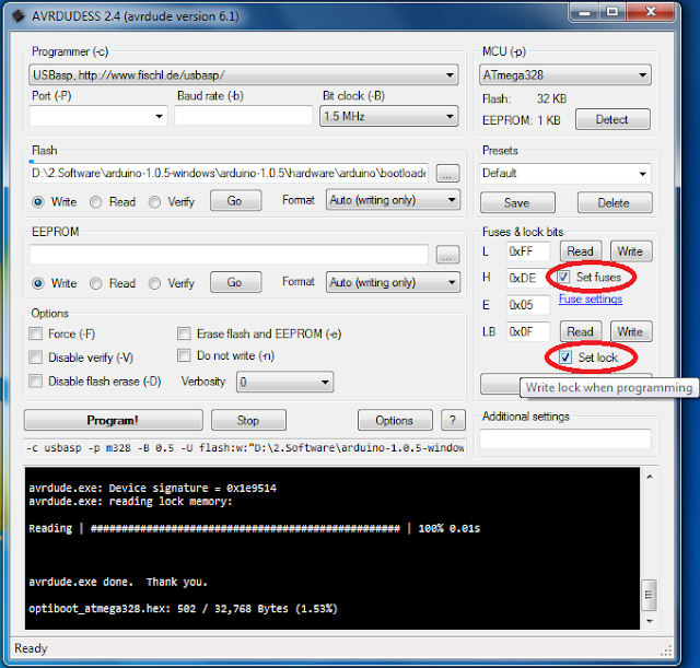
Now click on “Program!” button. It will take about 30 seconds. You can now use your cheap ATMega328 microcontroller as a regular Arduino.
You now have an Atmega328P that can be programmed with the Arduino IDE. Just plug in your new Atmega328P into any Arduino Uno board or using a USB to Serial Converter to upload your Arduino Sketch.
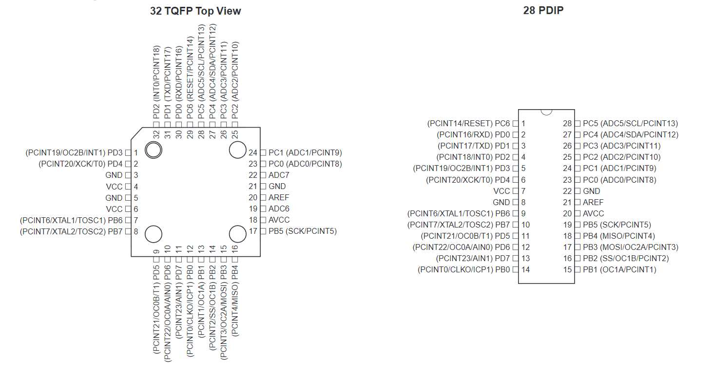
ATMega328 Pinout (TQFP and PDIP)
The schematic at the start of the post is for the 32 TQFP package and you can easily modify it for the 28 PDIP version using the following pinout.

The tutorial’s part list is sponsored by www.lcsc.com, the wholesale retail electronic components store in China. To learn more about LCSC.com read their company profile:
- Who we are: LCSC Electronics is one of the fastest growing suppliers of electronic components in China. LCSC Electronics has been committed to offering multitudinous, genuine and in-stock items, since its founding in 2011.
- Main Products: Our extensive product includes semiconductors, resistors, capacitors, diodes, inductors, connectors, transistors, and sensor.
- Line cards: LCSC purchasing teamwork persistently to select the Chinese trusted manufacturers according to a high standard. We have 72 authorized brands suppliers which are still increasing by time, 173 international brands and 489 Asian brands suppliers.
- Warehouse: LCSC Electronics has a self-owned modern component warehouse with 10,000 ㎡ by stocking more than 180,000 kinds of parts. LCSC’s project of building the Technology Industry Park with an area of 350,000 ㎡ was launched in Jiangsu in July 2018, which provides a solid foundation for the development of stocking and supply chain in the next 5-10 years and it is Asian largest in-store components warehouse.
- Shipping: In-stock orders are ready to be shipped in 4 hours and send out to each corner of the world by DHL, FedEx EMS, USPS, and other carriers.
RELATED POSTS
 17 February, 2021 AppSens’s BLE Wearable ECG Sensor Powered By Nordic nRF52832 Detects Arrhythmia
 24 March, 2022 Audio Line Driver using DRV135 with Balanced Output
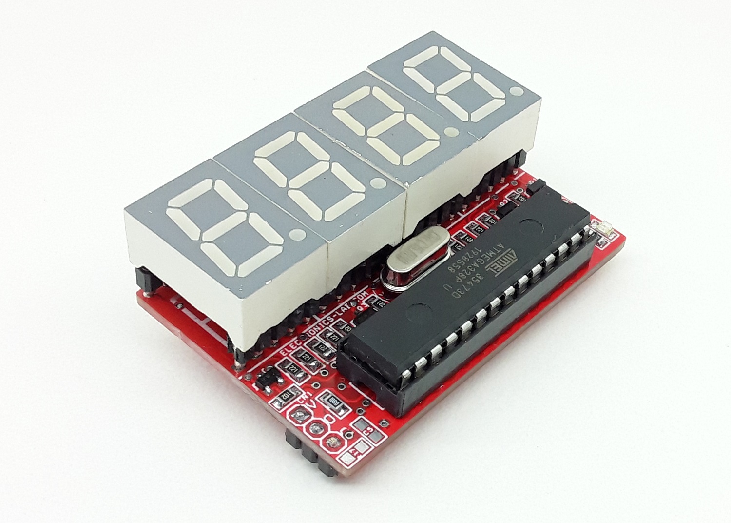 24 November, 2021 Arduino 4-Digit 0.5″ Common Cathode 7 Segment Display Module
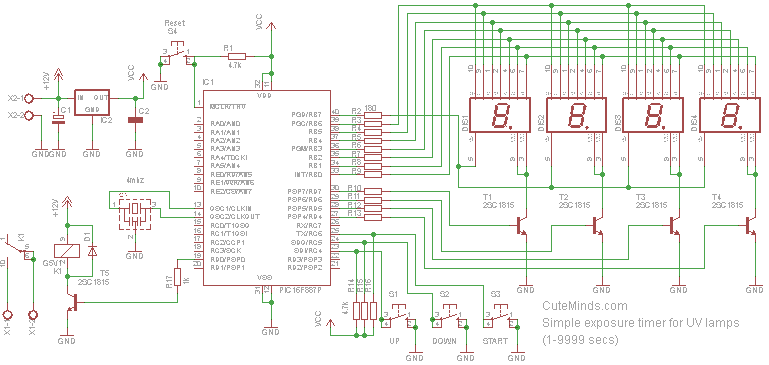 25 June, 2016 Count down timer for UV lamps using PIC16F887
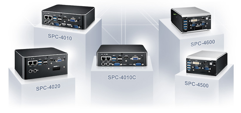 1 August, 2020 Vecow Unveils Energy-efficiency Ultra-compact Fanless Embedded Box PC
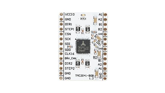 9 February, 2018 TMC2041-BOB – TMC2041 breakout board


There is an error in your diagram, Pin29 should be Pin 1(PCINT14/RESET) PC6
there is pin number 30 in atmega 328
This isn’t even a tutorial.
The article is updated.
Thanks a lot …As I didnt want to take out the atmega of my UNO everytime i bootloaded or programmed my microcontroller, this is the best way to do it.Also the PIn diagram I used was one from google.Please do check yours.Also a big thanks for the software…..
Can you show us, what circuit you used?
Apologies if I’m missing the obvious, but that does not appear to be the pin-out for the 28 pin DIP ATMega 328, but the pinout for the TQFP version. Might be worth making that clear? I suspect most people coming here would be assuming this would allow you to build your own, so would be assuming the DIP version. Indeed I see you link to the DIP version in your parts list.
Kevin
Good note Kevin, this is the TQFP version pinout. I have now included both pinouts on the post so it’s easy to link the connections for the DIP package and also fixed the parts list.
You said, ‘First of all wire up the circuit in breadboard as shown in below diagram’. But there is no diagram here. There are a lots of mess when it comes to USBASP programming of AVR MCUs out here on the internet. And you just added another one. I’m really confused.
It means the diagram above, on the beginning of the post.
WRONG SCHEMATICS! tqfp32 reset line is pin29, not 1!!! please update!
Thanks for pointing me to this error in schematic. I fixed it.
What would be the best avrdude configuration to run this chip in its lowest possible power consumption mode? No crystal etc.? Looking to use this chip (since I have 5 of them) in a PCB project. No UNO board at all.
Hello: Thank you very much for your contribution. I have been able to recover a “damaged” arduino board simply and quickly. The truth is that I have searched a lot on the internet, and your publication has been the best (and the only) that I have found. A big hug!!