

Function Generator Using AD9833 DDS – Arduino Compatible
- Rajkumar Sharma
- 378 Views
- medium
- Tested
- SKU: EL138837
- Quote Now
- 0 Likes

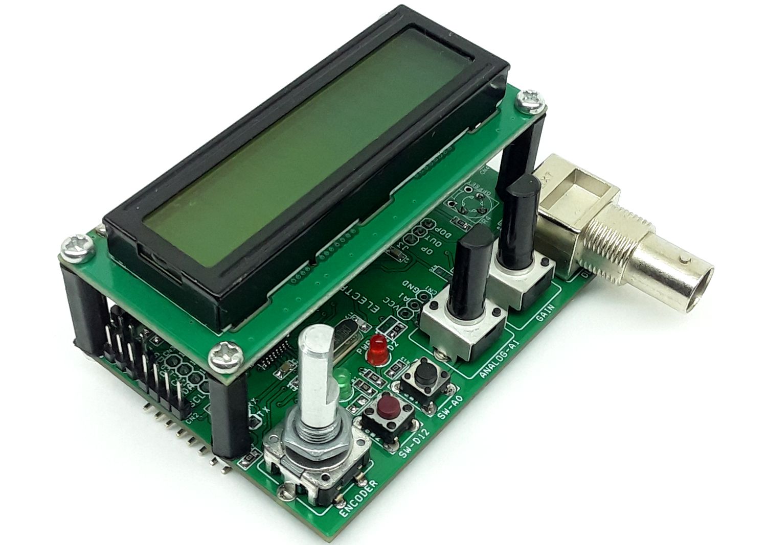
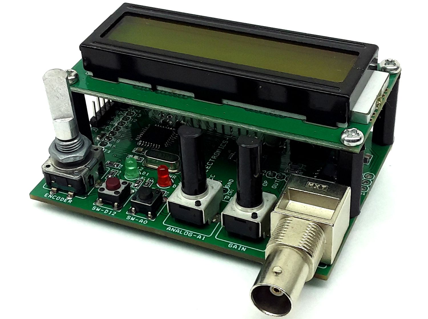
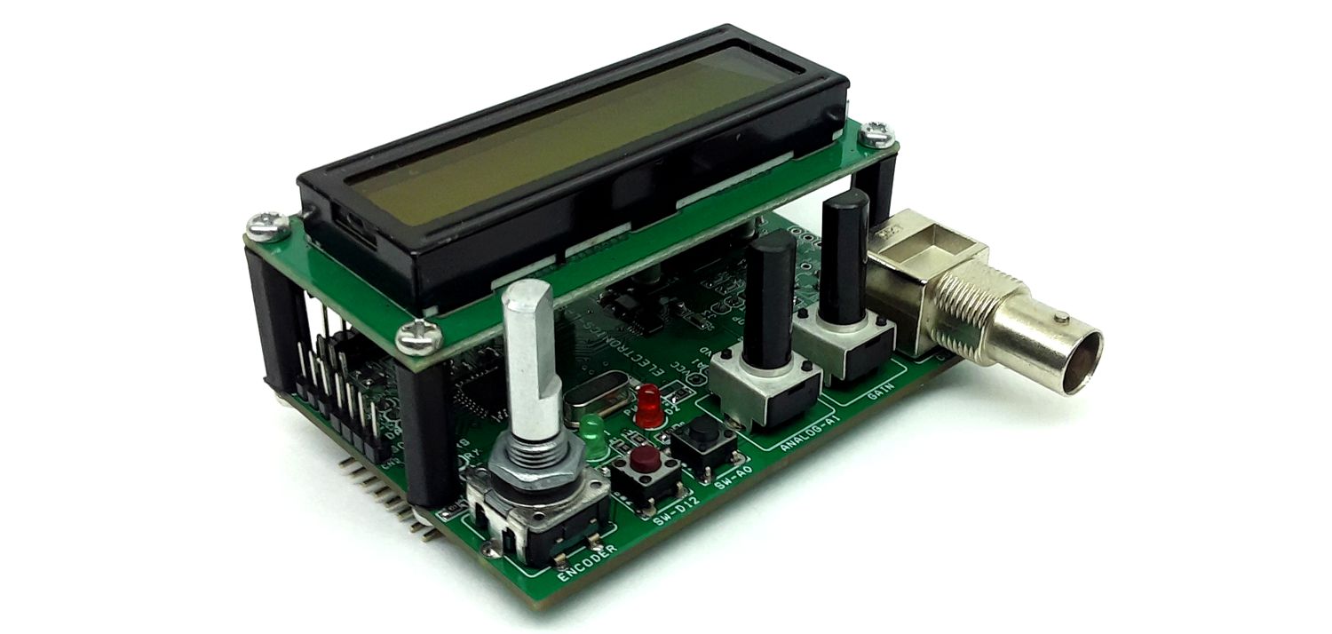
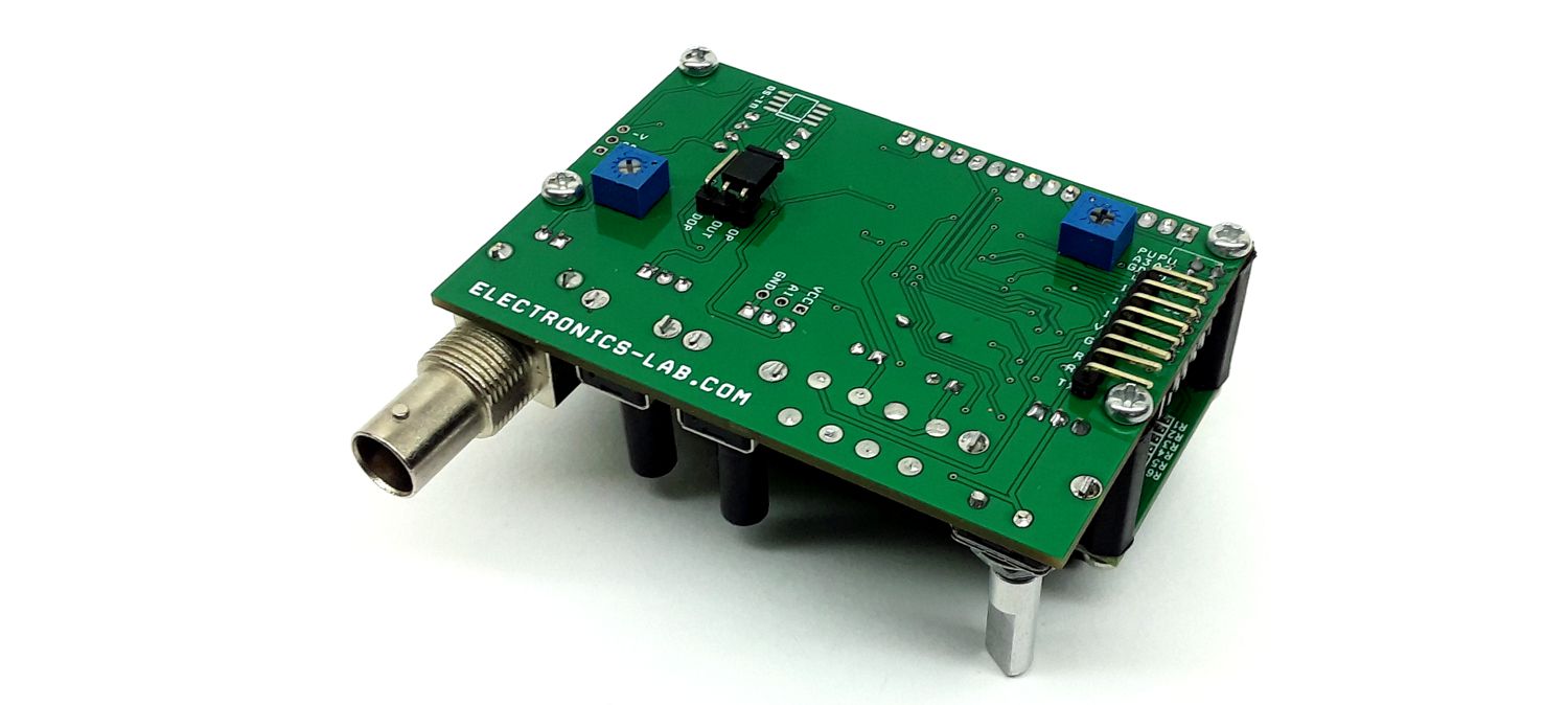
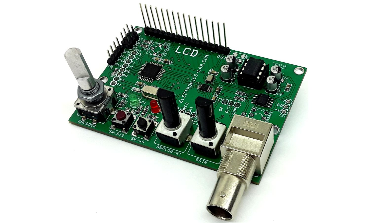
This is an Arduino-compatible hardware designed for building a low-cost function generator. The project consists of all the required spices to build your own function generator. It includes multiple options such as a potentiometer, rotary encoder, tactile switches, op-amp, and 16×2 LCD interface. The project can output sine, triangular, and square waves with gain adjustment and offset adjustment. The board works with a 5V single power supply.
Key Features
- Atmega328 TQPF microcontroller for Arduino IDE
- 16×2 LCD Parallel Interface Can be used to display Function Generator Menu
- Connector for I2C LCD Interface (Connector CN2)
- AD9833, DDS Function Generator Chip
- Dual Supply for Op-Amp Circuit to Increase Low Output Signal of AD9833 DDS Function Generator
- Potentiometer to Adjust the Gain of the Op-Amp
- Potentiometer On Analog Pin A0 (Can be used to Adjust the Frequency)
- Tactile Switch SW2 Connected Arduino A0 with an optional pull-up resistor
- Tactile Switch SW2 Connected Arduino D12 with an optional pull-up resistor
- Jumper J1 Arduino A3 Pin, with optional Pull Up Resistor
- Jumper J2 Arduino A2 Pin, with optional Pull Up Resistor
- Rotary Encoder U1 with Tactile Switch
- LED D2 Connected to Arduino D12
- Connector CN4 Dual Power Supply input for Op-amp, in case U1 MAX680 is not used
- Jumper J3, AD9833 Direct Output or Op-Amp Output Selection
- Trimmer Potentiometer PR4 to Adjust the Op-Amp Offset (Zero), DC Level Adjust
Features
- Power Supply 5V DC @ 120mA
- Optional Dual Supply Input for High Voltage Output Swing
- Output Sine, Triangular, and Square Wave
- Output Frequency Up to 12Mhz
- On Board Rotary Encoder for Menu and Frequency Control
- Gain and Offset Adjust Potentiometer
- On Board Parallel 16X2 LCD and I2C LCD Option
- LCD Contrast Adjust Trimmer Potentiometer
- BNC Connector for Output
- PCB Dimensions 80.01 x 55.88mm
- 4 x 3MM Mounting Holes for LCD
DC-DC Converter 5V Single Supply to Dual Output +/-10V Output
U1 MAX680 is a single supply to Dual supply converter. This chip provides a symmetric power supply +/-10V to OPAMP U4. A dual supply is required for Sine-Wave output, in the case of higher voltage output, use external dual power supply input through CN4, in this case, don’t install U1 Max680, capacitor C4, and capacitor C1.
OPAMP
The sine-Wave and Tringle-Wave outputs of AD9833 are very low and need amplification, U4 op-amp is provided to amplify the output of AD9833. This Op-Amp requires a dual supply. Output offset can be adjusted using PR4 trimmer potentiometer and gain adjust using potentiometer PR3. 1 to 20, Maximum output swing +/-7V, for higher voltage swing use external dual power supply for the op-amp, in this case, don’t install U1 MAX680.
AD9833
The AD9833 is a low-power, programmable waveform generator capable of producing sine, triangular, and square wave outputs. Waveform generation is required in various types of sensing, actuation, and time domain reflectometry (TDR) applications. The output frequency and phase are software-programmable, allowing easy tuning. No external components are needed. The frequency registers are 28 bits wide: with a 25 MHz clock rate, a resolution of 0.1 Hz can be achieved; with a 1 MHz clock rate, the AD9833 can be tuned to 0.004 Hz resolution.
The AD9833 is written via a 3-wire serial interface. This serial interface operates at clock rates up to 40 MHz and is compatible with DSP and microcontroller standards. The device operates with a power supply from 2.3 V to 5.5 V. The AD9833 has a power-down function (SLEEP). This function allows sections of the device that are not being used to be powered down, thus minimizing the current consumption of the part. For example, the DAC can be powered down when a clock output is being generated.
ATMEGA328 Programming
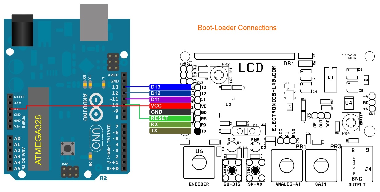
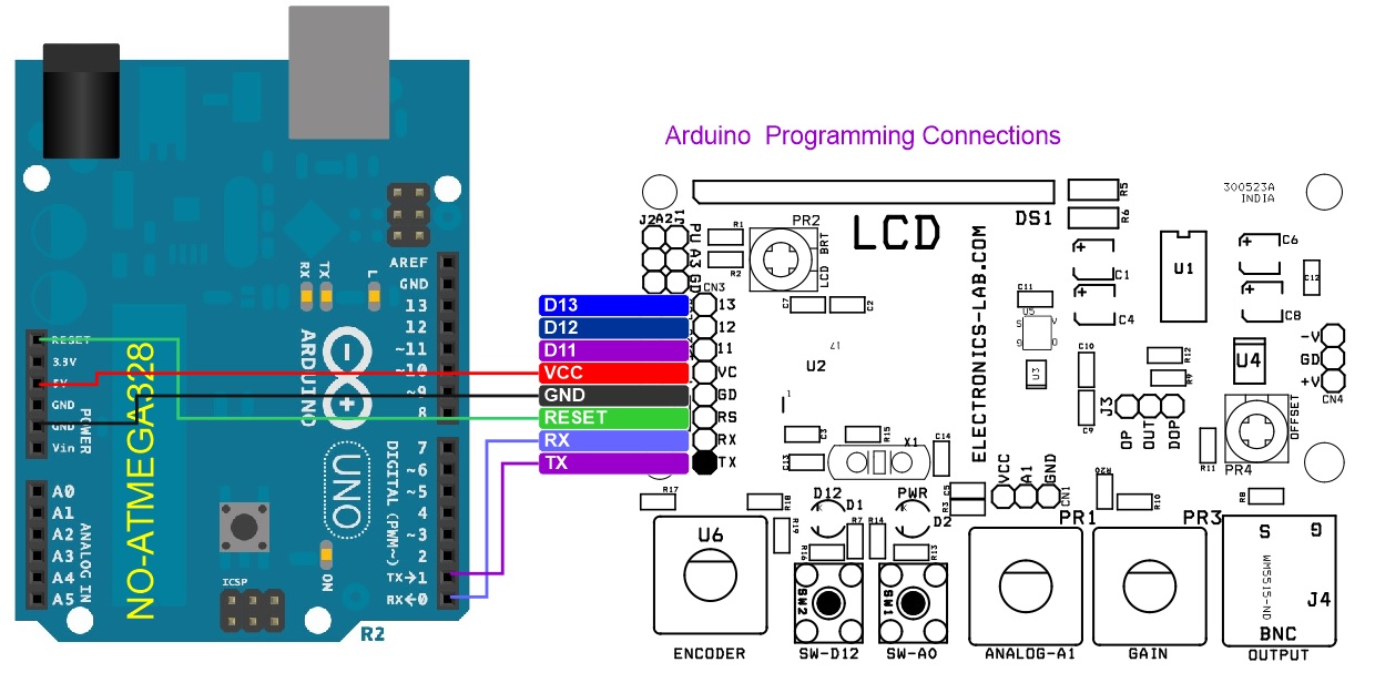
AVR micro-controller used to make the project Arduino compatible, all pin details are provided in schematics, a new chip can be programmed using Arduino IDE, Connector CN3 is provided to boot-loader and Arduino programming for the ATMEGA328. Refer to diagrams below.
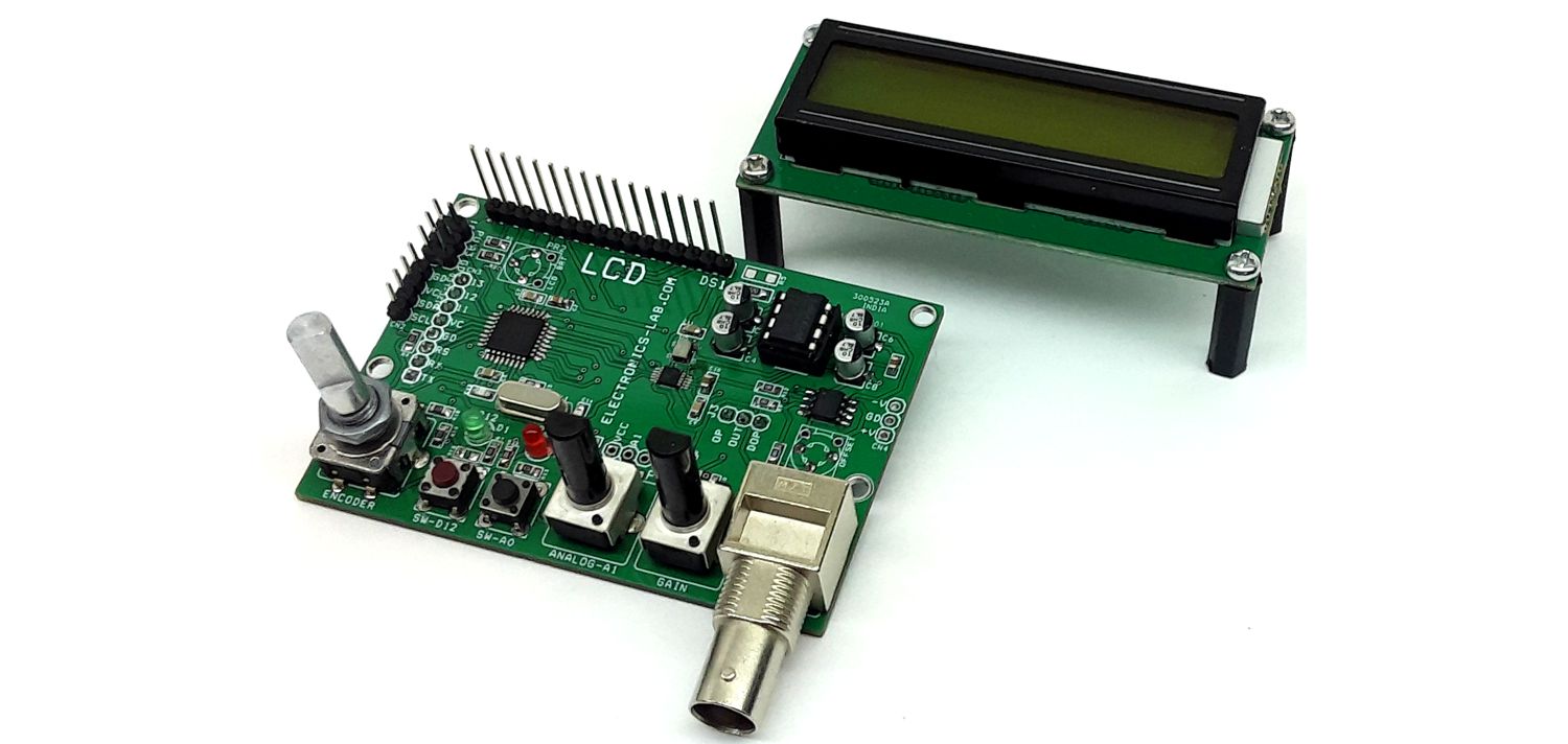
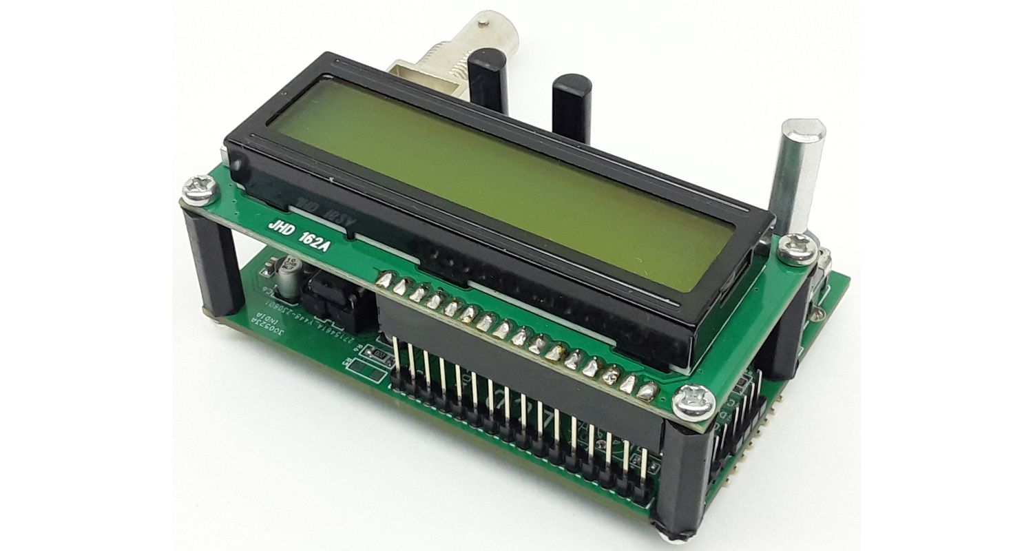
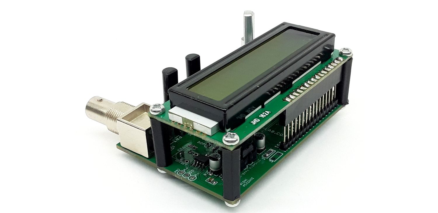
16×2 LCD Parallel Connections
The 16×2 LCD can be directly connected and installed on board using 4 Screws with the help of studs. The male header on the main board and female header on LCD provides an easy interface and LCD seats directly on the board. Trimmer PR2 can be used to adjust the contrast of LCD, LCD backlight is powered through current limiting resistor R5.
I2C serial LCD or OLED
I2C Serial LCD or OLED display can be connected to CN2 connector.
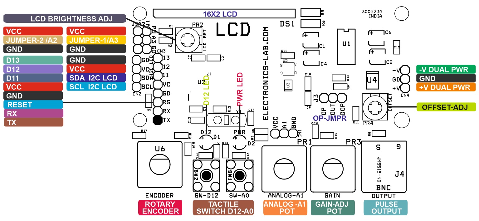
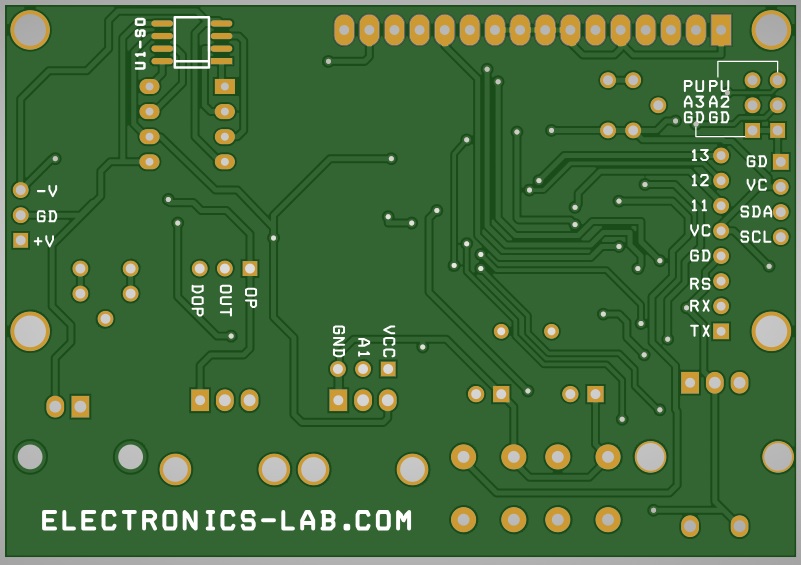
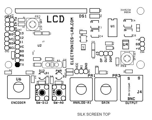
Connections and other details
- CN1: 3 Pin Male Header Connected to A1 pin of Arduino Pin 1 = VCC, Pin 2 = A1, Pin 3 = GND
- CN2: I2C LCD to OLED Display Interface Pin 1 = GND, Pin 2 = VCC, Pin 3 Arduino A4 SDA, Pin 4 Arduino A5 SCL
- CN3: Arduino Programming/Boot-Loader Connector Pin 1 = TX, Pin 2 = RX, Pin 3 = Reset, Pin 4 = GND, Pin 5 = VCC, Pin 6 D11, Pin 7 = D12, Pin 8 = D13
- CN4: Dual Power Supply Input for Op-Amp U4 optional, in case external power supply input (Do Not use MAX680 U4) If the board is powered from an external source
- PR1: On Board Potentiometer Connected to Arduino Analog A3
- PR2: Trimmer Potentiometer 16X2 LCD Brightness Adjust
- PR3: Potentiometer to Adjust Op-Amp Gain
- PR4: Trimmer Potentiometer DC Offset Adjust Op-Amp U4
- SW1: Tactile Switch Arduino A0 with Optional Pullup Resistor R13 (This Switch Can not be used if 16X2 LCD is used, they share the A0 Pin)
- SW2: Tactile Switch Arduino D12 with Optional Pullup Resistor R16
- U6: Rotary Encoder with Top Tactile Switch Channel-A Arduino D6, Channel-B Arduino D7, Knob Tactile Switch D8
- D1: Power LED
- D2: Optional LED Connected to Arduino Pin 12D
- J4: BNC Connector – Signal Output (Sine-Wave, Triangle Wave, Square Wave)
- AD9833: Arduino D10 >> AD9833 FSYNC, Arduino D11 >> AD9833 SDATA, Arduino D13 >> AD9833 SCLK
- 16×2 LCD: Arduino D2 > LCD DB7, Arduino D3 > LCD DB6, Arduino D4 > LCD DB5, Arduino D5 > LCD DB4, Arduino D9 > LCD ENB, Arduino A0 > LCD RS
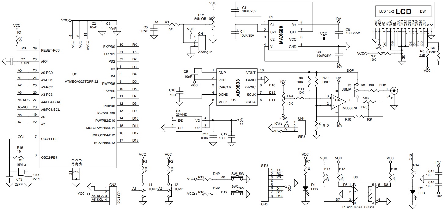
Schematic
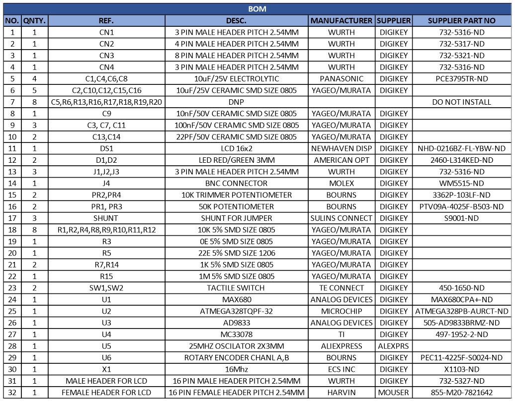
Parts List
| NO. | QNTY. | REF. | DESC. | MANUFACTURER | SUPPLIER | SUPPLIER PART NO |
|---|---|---|---|---|---|---|
| 1 | 1 | CN1 | 3 PIN MALE HEADER PITCH 2.54MM | WURTH | DIGIKEY | 732-5316-ND |
| 2 | 1 | CN2 | 4 PIN MALE HEADER PITCH 2.54MM | WURTH | DIGIKEY | 732-5317-ND |
| 3 | 1 | CN3 | 8 PIN MALE HEADER PITCH 2.54MM | WURTH | DIGIKEY | 732-5321-ND |
| 4 | 1 | CN4 | 3 PIN MALE HEADER PITCH 2.54MM | WURTH | DIGIKEY | 732-5316-ND |
| 5 | 4 | C1,C4,C6,C8 | 10uF/25V ELECTROLYTIC | PANASONIC | DIGIKEY | PCE3795TR-ND |
| 6 | 5 | C2,C10,C12,C15,C16 | 10uF/25V CERAMIC SMD SIZE 0805 | YAGEO/MURATA | DIGIKEY | |
| 7 | 8 | C5,R6,R13,R16,R17,R18,R19,R20 | DNP | DO NOT INSTALL | ||
| 8 | 1 | C9 | 10nF/50V CERAMIC SMD SIZE 0805 | YAGEO/MURATA | DIGIKEY | |
| 9 | 3 | C3, C7, C11 | 100nF/50V CERAMIC SMD SIZE 0805 | YAGEO/MURATA | DIGIKEY | |
| 10 | 2 | C13,C14 | 22PF/50V CERAMIC SMD SIZE 0805 | YAGEO/MURATA | DIGIKEY | |
| 11 | 1 | DS1 | LCD 16x2 | NEWHAVEN DISP | DIGIKEY | NHD-0216BZ-FL-YBW-ND |
| 12 | 2 | D1,D2 | LED RED/GREEN 3MM | AMERICAN OPT | DIGIKEY | 2460-L314KED-ND |
| 13 | 3 | J1,J2,J3 | 3 PIN MALE HEADER PITCH 2.54MM | WURTH | DIGIKEY | 732-5316-ND |
| 14 | 1 | J4 | BNC CONNECTOR | MOLEX | DIGIKEY | WM5515-ND |
| 15 | 2 | PR2,PR4 | 10K TRIMMER POTENTIOMETER | BOURNS | DIGIKEY | 3362P-103LF-ND |
| 16 | 2 | PR1, PR3 | 50K POTENTIOMETER | BOURNS | DIGIKEY | PTV09A-4025F-B503-ND |
| 17 | 3 | SHUNT | SHUNT FOR JUMPER | SULINS CONNECT | DIGIKEY | S9001-ND |
| 18 | 8 | R1,R2,R4,R8,R9,R10,R11,R12 | 10K 5% SMD SIZE 0805 | YAGEO/MURATA | DIGIKEY | |
| 19 | 1 | R3 | 0E 5% SMD SIZE 0805 | YAGEO/MURATA | DIGIKEY | |
| 20 | 1 | R5 | 22E 5% SMD SIZE 1206 | YAGEO/MURATA | DIGIKEY | |
| 21 | 2 | R7,R14 | 1K 5% SMD SIZE 0805 | YAGEO/MURATA | DIGIKEY | |
| 22 | 1 | R15 | 1M 5% SMD SIZE 0805 | YAGEO/MURATA | DIGIKEY | |
| 23 | 2 | SW1,SW2 | TACTILE SWITCH | TE CONNECT | DIGIKEY | 450-1650-ND |
| 24 | 1 | U1 | MAX680 | ANALOG DEVICES | DIGIKEY | MAX680CPA+-ND |
| 25 | 1 | U2 | ATMEGA328TQPF-32 | MICROCHIP | DIGIKEY | ATMEGA328PB-AURCT-ND |
| 26 | 1 | U3 | AD9833 | ANALOG DEVICES | DIGIKEY | 505-AD9833BRMZ-ND |
| 27 | 1 | U4 | MC33078 | TI | DIGIKEY | 497-1952-2-ND |
| 28 | 1 | U5 | 25MHZ OSCILATOR 2X3MM | ALIEXPRESS | ALEXPRS | |
| 29 | 1 | U6 | ROTARY ENCODER CHANL A,B | BOURNS | DIGIKEY | PEC11-4225F-S0024-ND |
| 30 | 1 | X1 | 16Mhz | ECS INC | DIGIKEY | X1103-ND |
| 31 | 1 | MALE HEADER FOR LCD | 16 PIN MALE HEADER PITCH 2.54MM | WURTH | DIGIKEY | 732-5327-ND |
| 32 | 1 | FEMALE HEADER FOR LCD | 16 PIN FEMALE HEADER PITCH 2.54MM | HARVIN | MOUSER | 855-M20-7821642 |
Connections
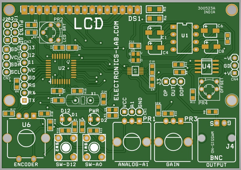
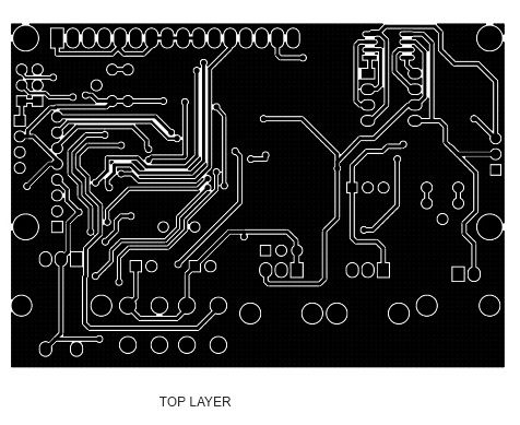
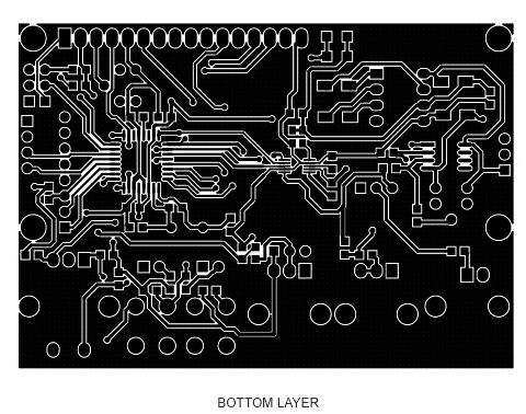
Gerber View
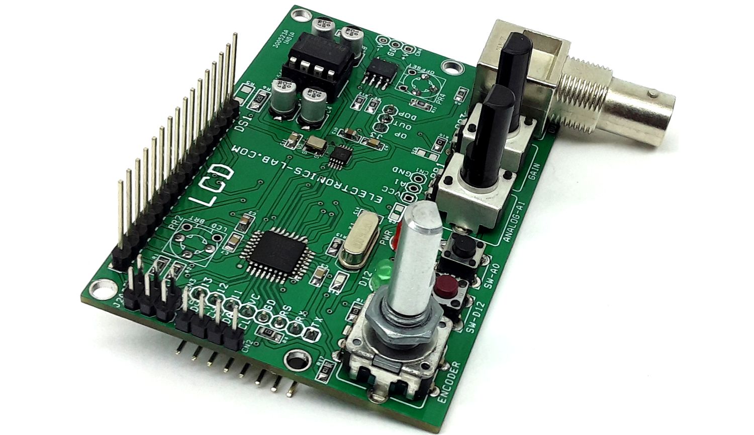
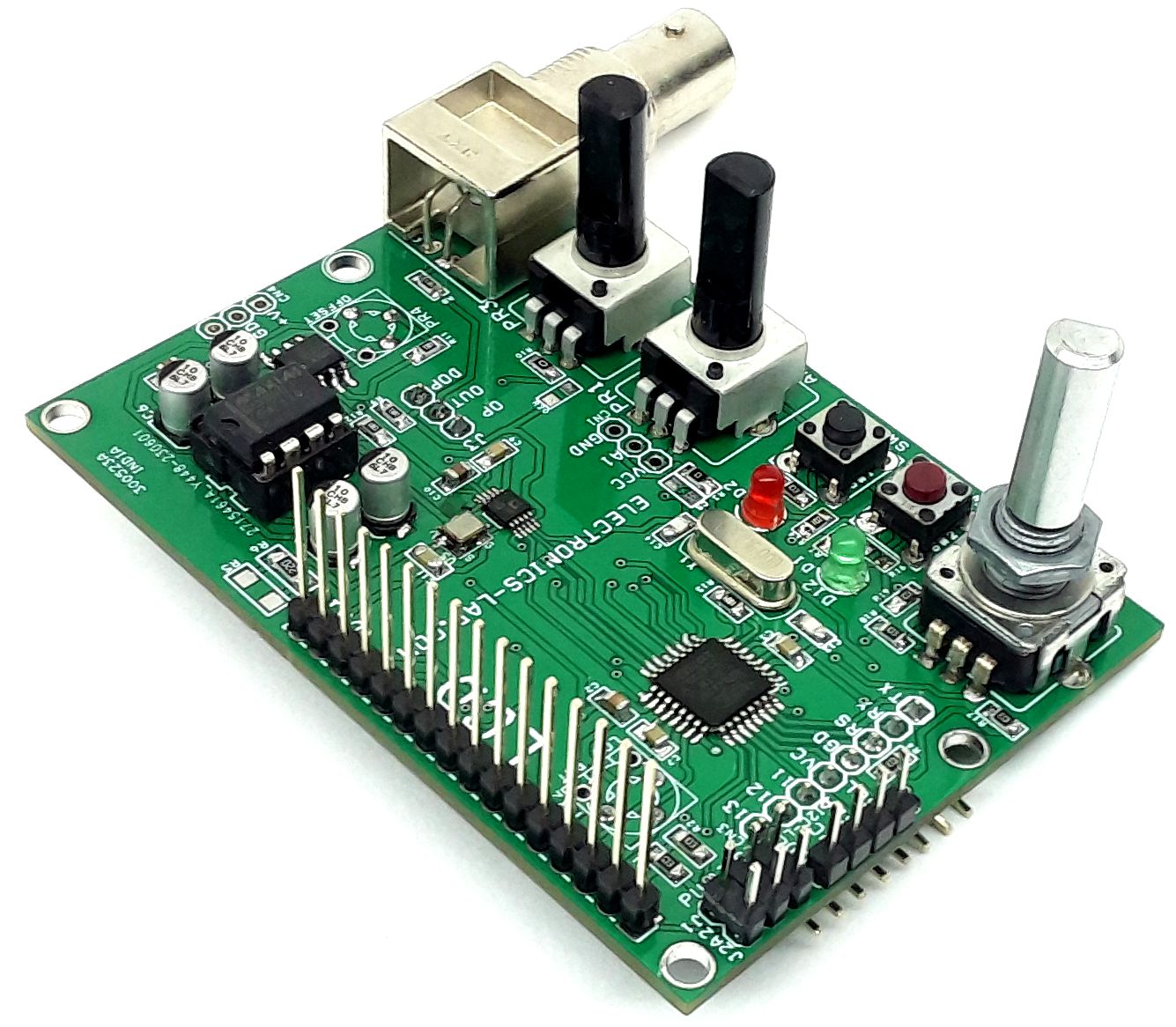
Photos
AD9833 Datasheet
PCB


 Converter")
