

High Power LED mood Lamp
- Toon Beerten
- http://tobe.nimio.info
- 45.351 Views
- moderate
- Tested
- 0 Likes

Introduction
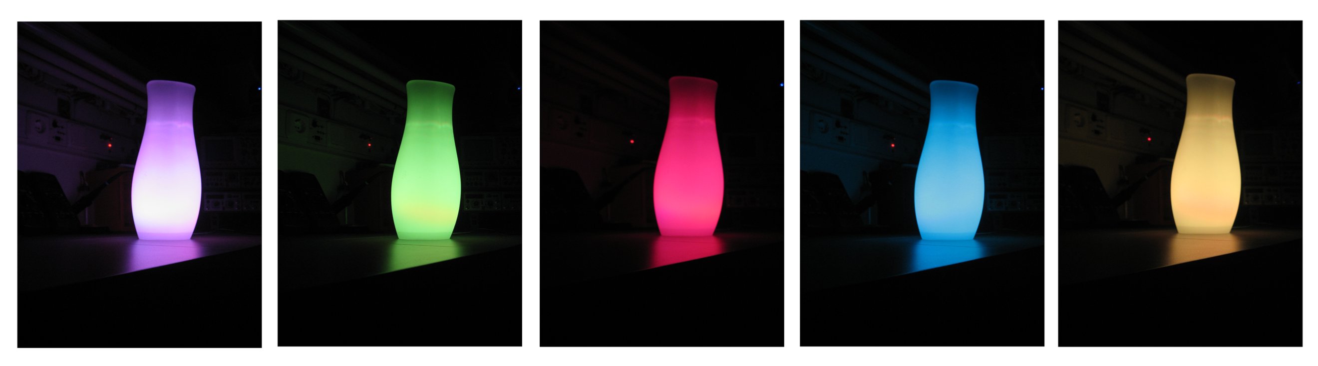
In this page we will introduce a great project designed by Toon Beerten. His project named “DIY Led Mood Lamp” can become a very interesting add-on for your room that’s absolutely sure it will impress everyone. As you can see on the photos, we talk about a color fading lamp, that looks amazing!
The purpose of this page is to try to give some hints building it successful. This high power led mood light is based on PIC16F628 and the ability of this mcu to produce PWM pulses. Varying pulse width we can produce millions of color combinations using only the three basic colors. So only one RGB (Red-Green-Blue) led is capable producing a rainbow of fading colors.
With the help of four switches we can handle all functions of the lamp. We can choose fading or jumping between colors, we can select a rainbow style or a random color changing behavior, we can choose slow or fast changing of colors and we can pause on a desired color.
Finally we will make some power dissipation measurements to help us select an appropriate power supply unit.
Housing
You can use your imagination to find a housing that will be able to diffuse colors uniformly. Color difussion is necessary to achieve best results. In original design the author used the 45cm IKEA Mylonit lamp. That’s a great housing for your lamp. Instead you can use the smaller 31cm IKEA Mylonit lamp with the same amazing results. That’s the lamp we used in our construction.

In our research we found other lamps (ex. sphere shape) that are ideal for housing your big led.
High Power LED
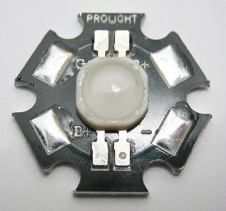
The led used is a high power 3W RGB LED. It can be found on ebay at LEDSEE-electronics. You can also check ebay for other high power RGB leds. It will do the jod the same way. Details of this brilliant led shown below.
3W high power RGB LED
Light Angle of the LED 140 degree°
Nominal current B,G,R 350mA
Forward voltage:
Red Typ 2,2V
Green Typ 3,55V
Blue Typ 3,55V
Wavelength of the LEDs:
Red Typ 625nm
Green Typ 530nm
Blue Typ 470nm
Luminous Intensity:
RED Typ 32lm
Green Typ 35lm
Blue Typ 10lm
LED type: Common Anode
Schematic
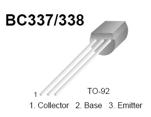
The schematic used is shown in the next image. It’s as simple as it shows. Take care on the correct transistor mount and correct polarity of power source.
Parts List
Here is a list of the components i used for making the led mood lamp.
- 3 x NPN transistors capable of driving 500 mA, for example the BC337
- one PIC 16F628(A) and a programmer
- a small perforated circuit board
- 7 x 10K resistors (1/4W)
- 1/2 watt resistors (2x 22 Ohm, 4x 10 Ohm) and a DIP switch
- a power supply (5 volts, 500 mA)
- Ikea Mylonit lamp or other housing
- silicon paste from your local DIY shop (if you want to use a heatsink)
- one z-power 3 watt rgb led
- a little heatsink and some cooling paste (if you want to use a heatsink)
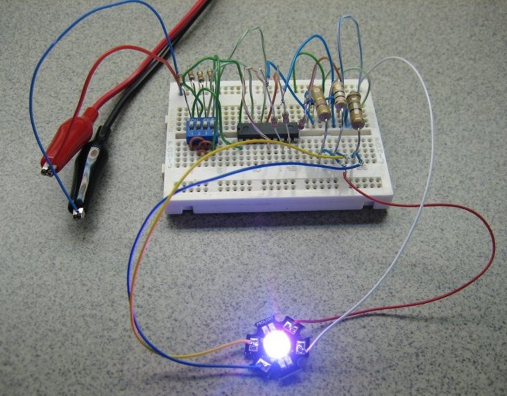
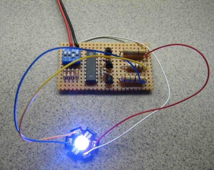
Circuit board
On the next image you can see the circuit arranged on a perforated board.
Programming The PIC 16F628 Microprocessor
Programming the PIC16F628 can be achieved using this very simple pic programmer and a program called ic-prog. Just use your programmer and upload the .hex file on your PIC. For successful results you should pay attention on the fuse bits. You should enter the correct fuses as noted on the following table.
Fuses
IntRC I/O = Enabled
PWRT = Enabled
BODEN = Enabled
MCLR = Disabled
Rest of fuses = Disabled
DIP Switches functions
SW1 – makes you choose between G->GB->B->BR->R->RG–>>G effect and random color change effect
SW2 – makes you choose between fading and jumping from one color to another
SW3 – makes you choose between slow or fast
SW4 – pauses at the current color displayed
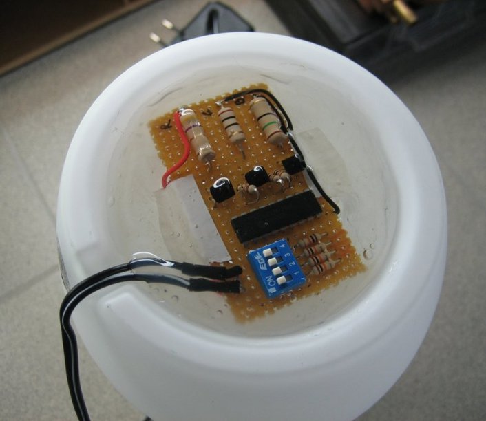
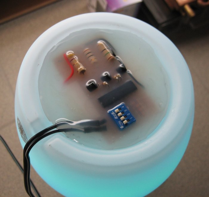
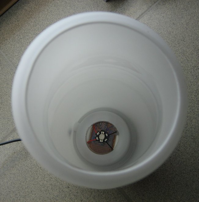
Mounting
A good way to mount the circuit board is to use a hot glue gun to “mold” the circuit underneath the lamp housing. There is plenty of space there for your board. At the next photos you can see the circuit board mounted on the small 31cm IKEA Mylonit Lamp.
Update – 10/2009
Steve Rougier made improvements on the original code and schematic adding additional operation modes. For detailed info and for updated source code check on this zip file: rougier


Not working even when correct connection is made
I’ve build this project and it works correctly
I’m looking a PWM driven LEDs circuit. Is this circuit would be working well for 1khz PWM by PIC 16F series?
I’m using a different programmer (TL866A) and I’m bit confused with FUSES. It’s totally different from IC-prog. as it uses config word. I have tried 3F50h but it doesn’t work.
Hello, I have built this circuit numerous times and the LED’S are not bright.Also looking at the ASM file, it shows a PIC16F84A not a PIC16F628A as in the diagram. I am using the right file and using a PICKIT 2 programmer.What is the problem? The switches seem to do nothing
Which file did you used to program the PIC? There is no ASM file on the download above.
Is code for AVR Atmega 32 available
We are sorry, this is a PIC based project
if i want to use more number LED’s simultaneously then what changes have to be done with the components.
or i should connect them in parallel/series.
also tell me how to increase the color changing time intervel
Hello.
I have tried in breadboard with small/ ordinary leds – no transistor, it works very well.
However, if I added BD135 with power leds, only blinding and no operating properly.
The problem: pic output ports couldn’t provide efficient base current to drive to transistors.
Solution: add more transistors to build pairs with darlington connection, the circuit would work well.