

8 Channel RS485 Relay Board
- Rajkumar Sharma
- 42.288 Views
- medium
- Tested
- SKU: EL52278
- Quote Now
- 0 Likes

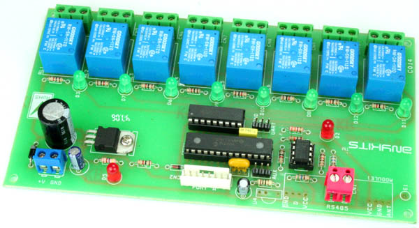
This project helps you control 8 relays using RS485 link with the help of a PC. This kit can effectively convert a standard PC to a powerful PLC ( programmable logic controller ). At the PC end , you will need to use our RS232 to RS485 Interface or any other suitable RS232 to RS485 Converter.
The project can offer a low-cost serial relay contact interface, easy to use with Visual Basic, Basic, C, Labview, Testpoint, or other high level languages that allow access to a serial port.
You can simply use the accompanying software provided with this project or issue control commands using any popular Terminal Port software available on the net.
The Serial port on the computer should be configured to 2400 baud – 8 bit words – 1 stop bit – no parity
RELAY OUTPUT COMMAND SUMMARY
RBnc – “RB” preamble, n – Relay number (1 to 8) and c – set/reset (1 – set, 0 – reset)
RS485 cable connects at CN1 connector. The setting or resetting of the relays is indicated by the associated LED’s close to them. LED D2 blinks to indicate a valid command received. LED D5 is the Power On Board Indicator.
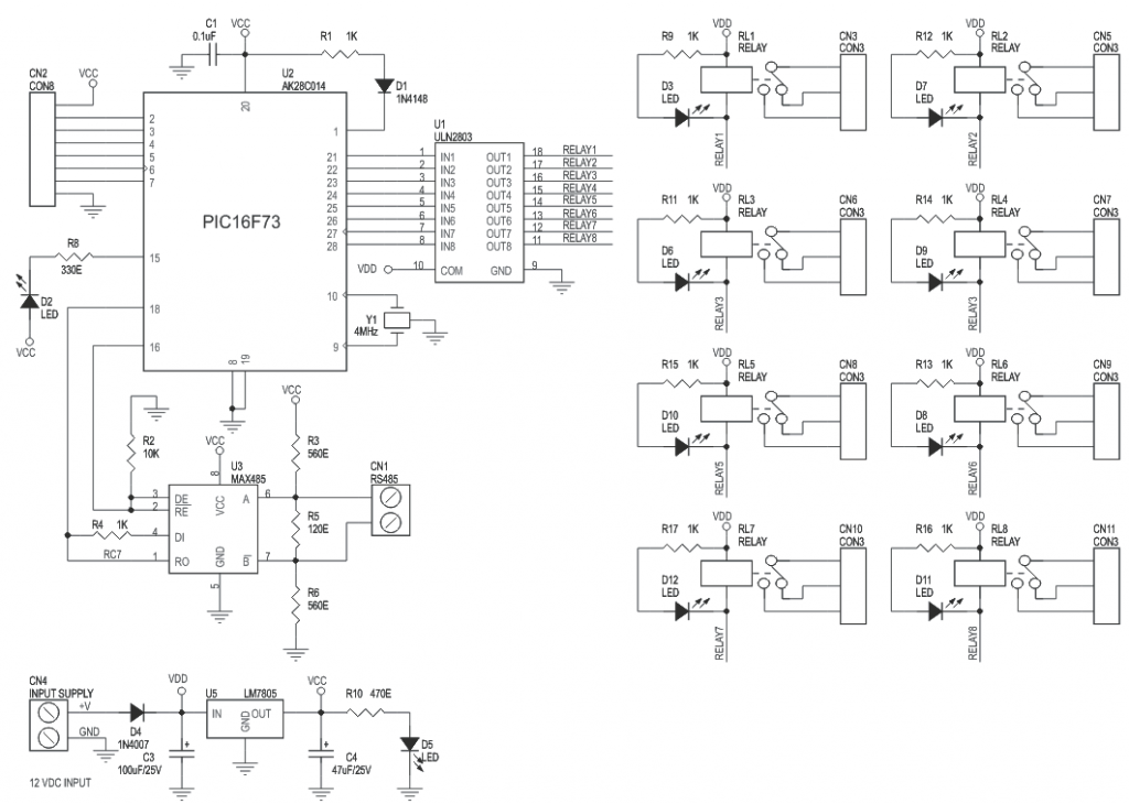
Please refer to the schematic diagram for the configuration of this board.
With RS485 Controlled 8 Relay Board you can control up to 8 SPDT (Single Pole Double Throw) relays using a simple RS485 protocol.
Features
- Up to 8, 12V SPDT relay control
- Industry standard relay drive IC – ULN2803
- Data received indicator LED
- LED indicator to display relay state
- Power-On LED indicator
- Onboard regulator IC
- Screw terminal type connector for easy connection of all wires to the PCB
- Simple RS485 Protocol
- Can be controlled either by a microcontroller board or via PC using suitable RS232 – RS485 converter
- Diode protection against reverse polarity connection
- NC-C-NO pin outs from each relay into a screw terminal connector
- Four mounting holes of 3.2 mm each
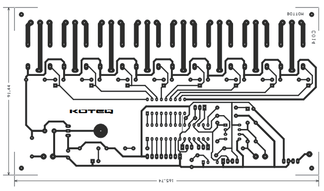
- PCB dimensions 166 mm x 92 mm
- Supply Voltage : 12 ~ 15 V DC
- I/O Voltage : 5 V DC
Schematic
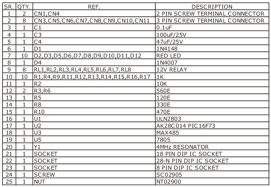
Parts List
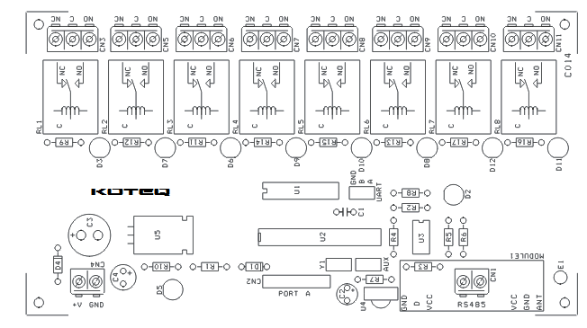
PCB


can you share with us the program file in c
We are sorry, the source code isn’t available for this project.
I have a full project with source and demonstration video. Here:
R7, C2 and U4 are considered in PCB file and real photo, but there aren’t in schematic drawing. Are they important? should we use them?!
The board has an optional InfraRed sensor, RF Receiver for RF/IR Remote application if don’t need to be implemented, you can omit those parts.
how to operate multiple modules like this in a single RS485 system