

Audio Oscillator with Frequency Counter
- Hristo
- http://diyfan.blogspot.com
- xristost@yahoo.com
- 15.217 Views
- moderate
- Tested
- 0 Likes

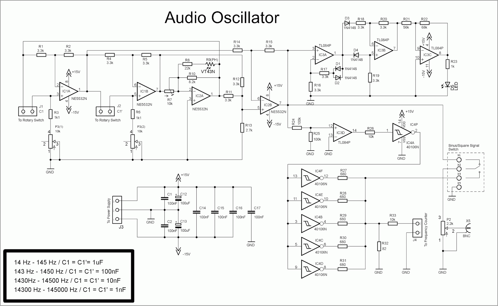
This project is not completely new. In fact, the oscillator is made from the same schematic as in one of my previous projects and only the frequency counter is made with different schematic.
After I finished the oscillator, I made some minor changes in the square signal part of the schematic. I connected five of the inverters in parallel with low value load resistors, thus reducing the influence of the parasitic capacitance of the PCB. The goal is to lower rise and fall times of square signal. Max output voltage in square signal mode is around 5V.
Schematic
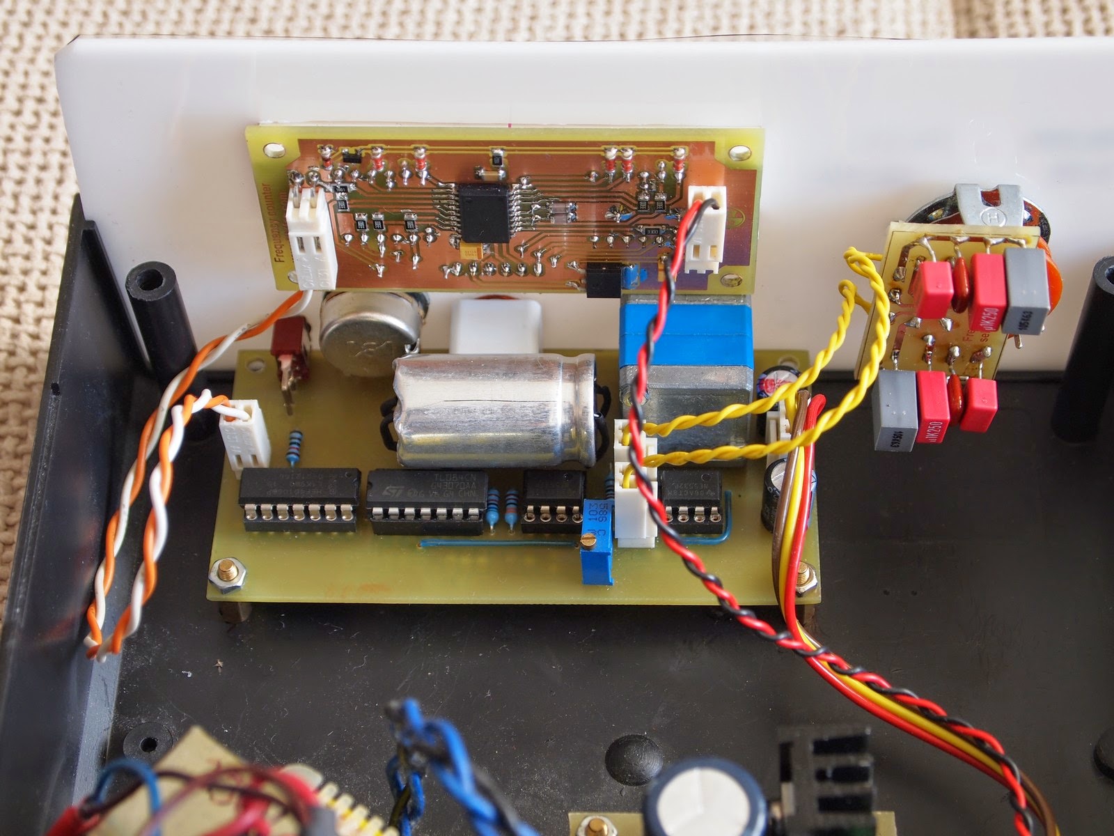
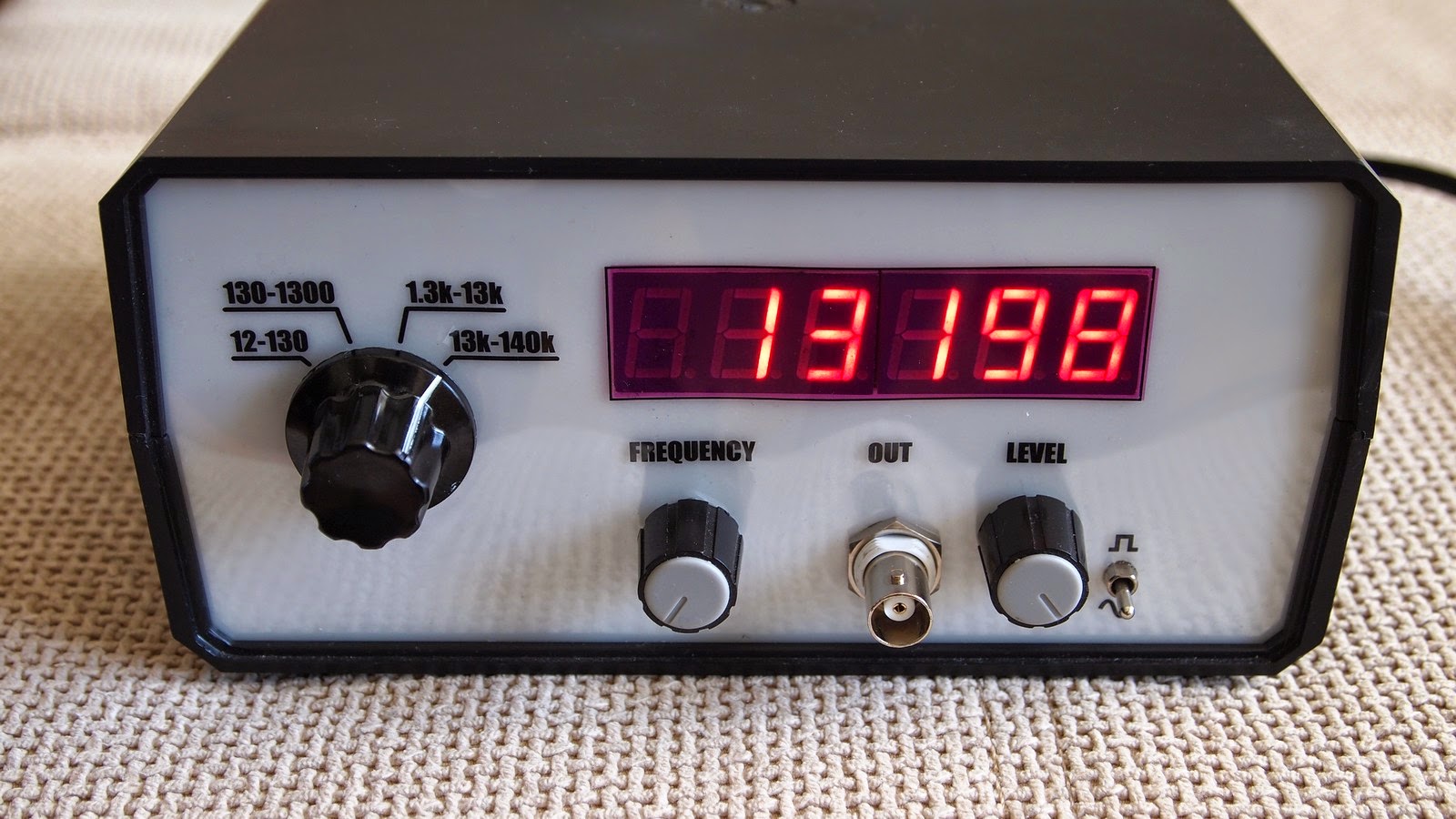
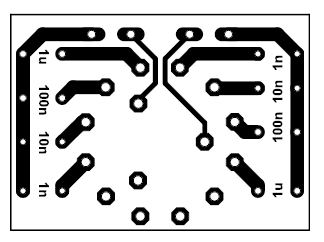
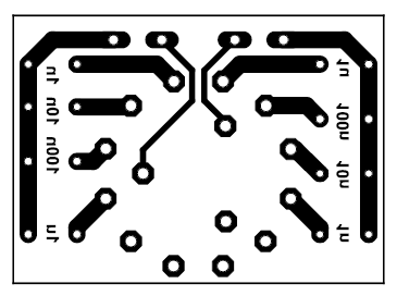
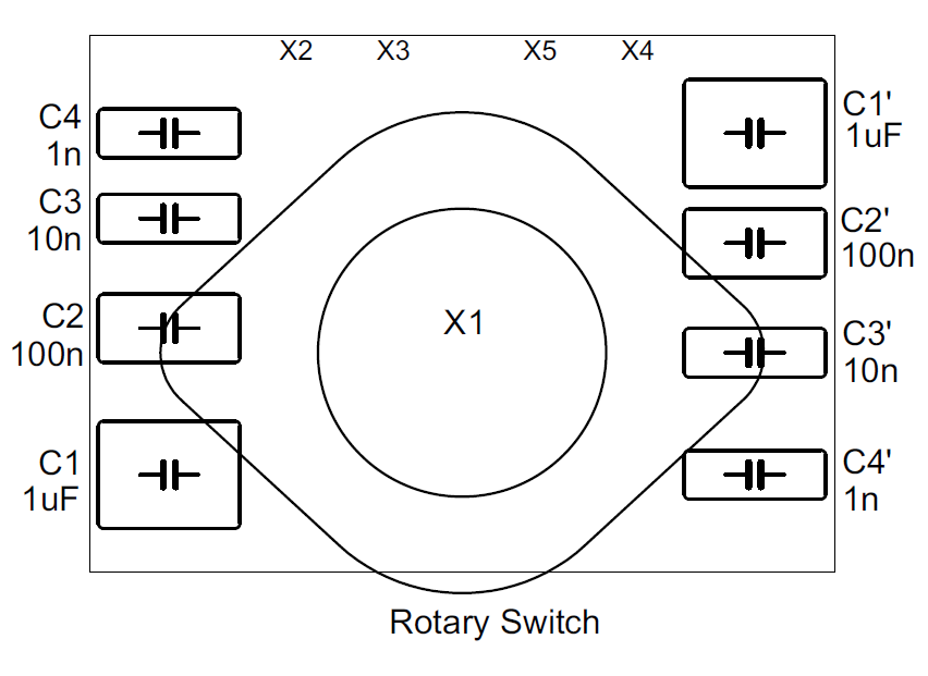
The oscillator have 4 ranges which are switched with external 3-pole/4-position rotary switch, connected this way:
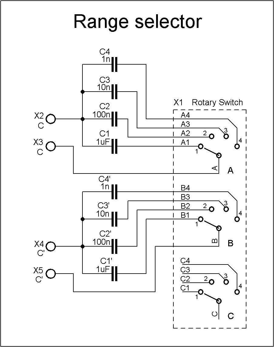
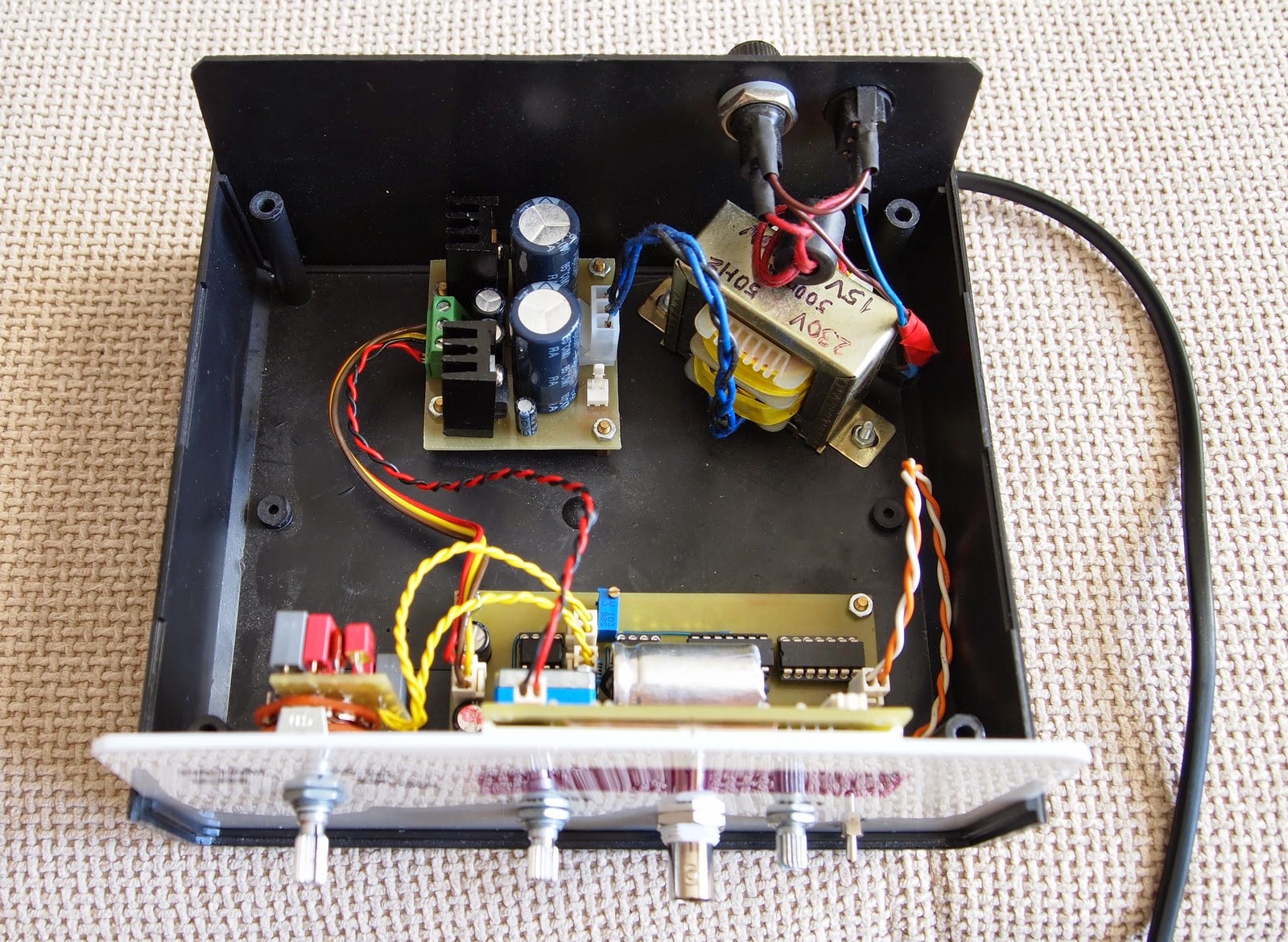
This module is connected via short cables to the respective connectors on the oscillator board.
Notice, that capacitors are soldered from the bottom side of this little board. The leads of the capacitors must be cut clean from the other side of the board for they do not touch the rotary switch
The photoresistor R9 and LED D5 form a negative feedback and must be put together in some isolated enclosure. I used an aluminum casing from a big electrolytic capacitor for this purpose. LED is standard 5mm red and for the photoresistor I used a TESLA brand piece (not sure what is the exact model). Other types of photoresistors should also work.
In the schematic the photoresistor is connected with one resistor (R8) in series and one (R10) in parallel. I found that in my case the oscillator work better without these 2 resistors.
Photos
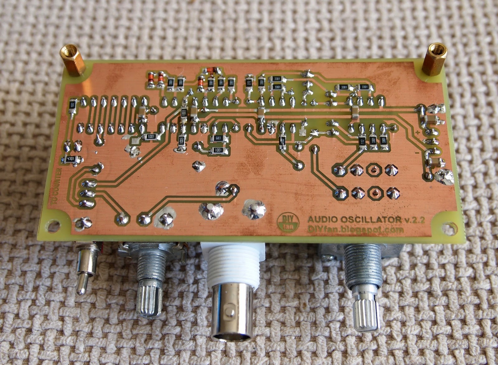
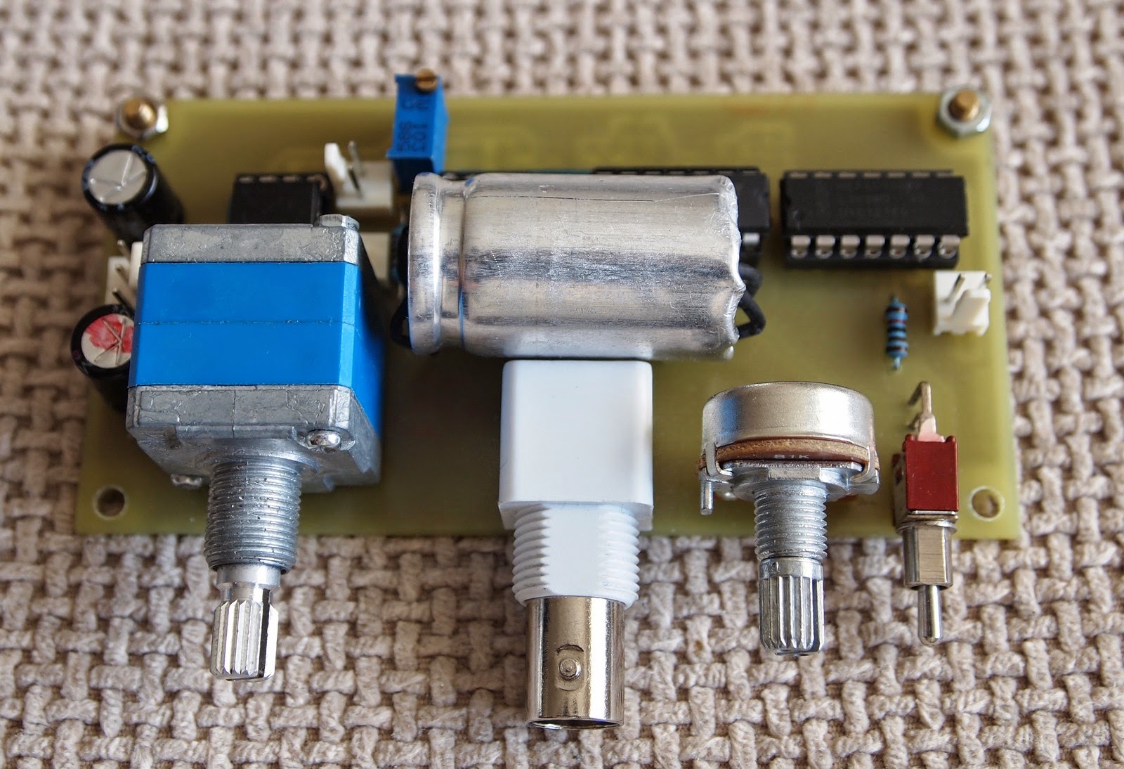
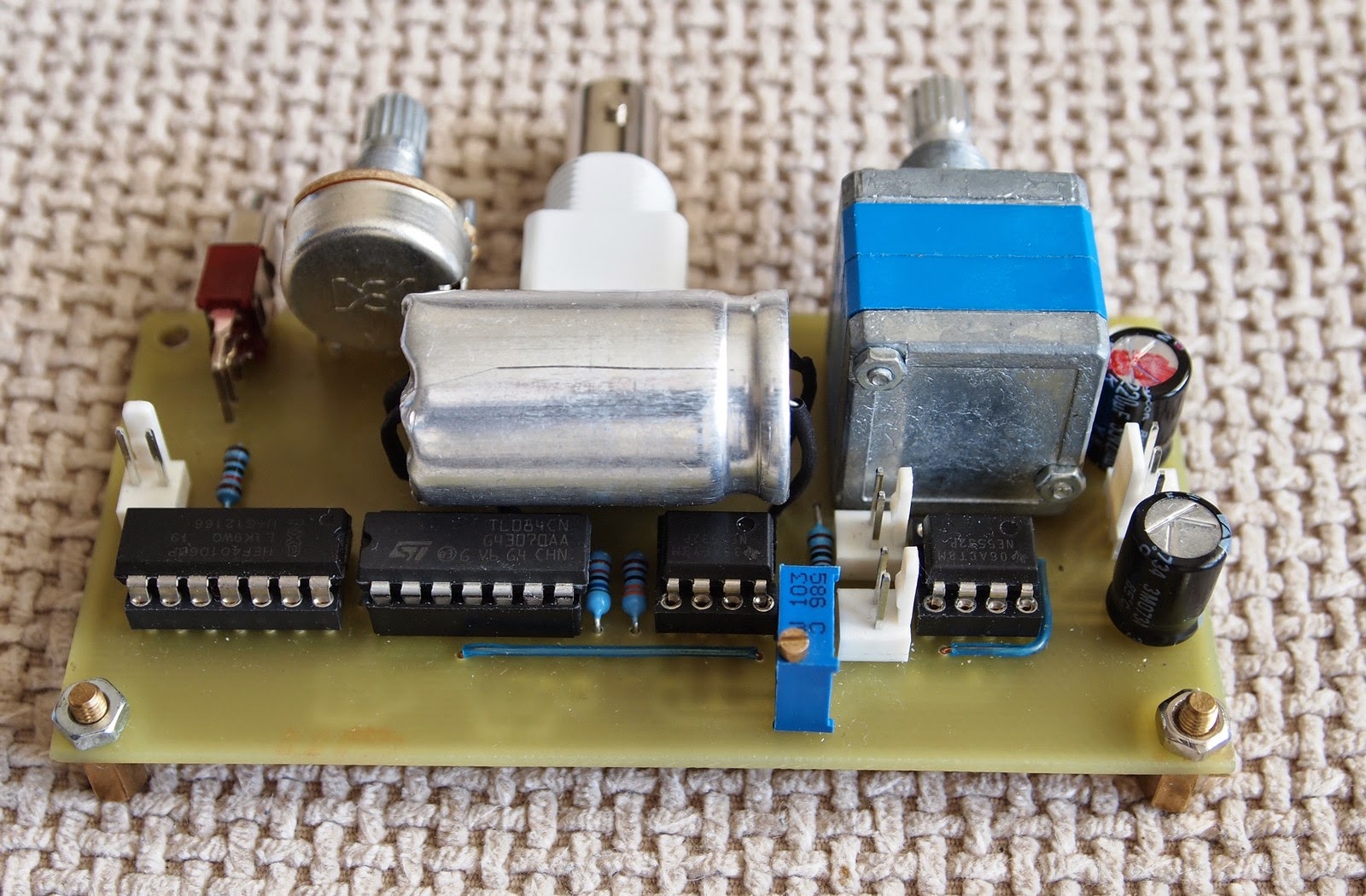
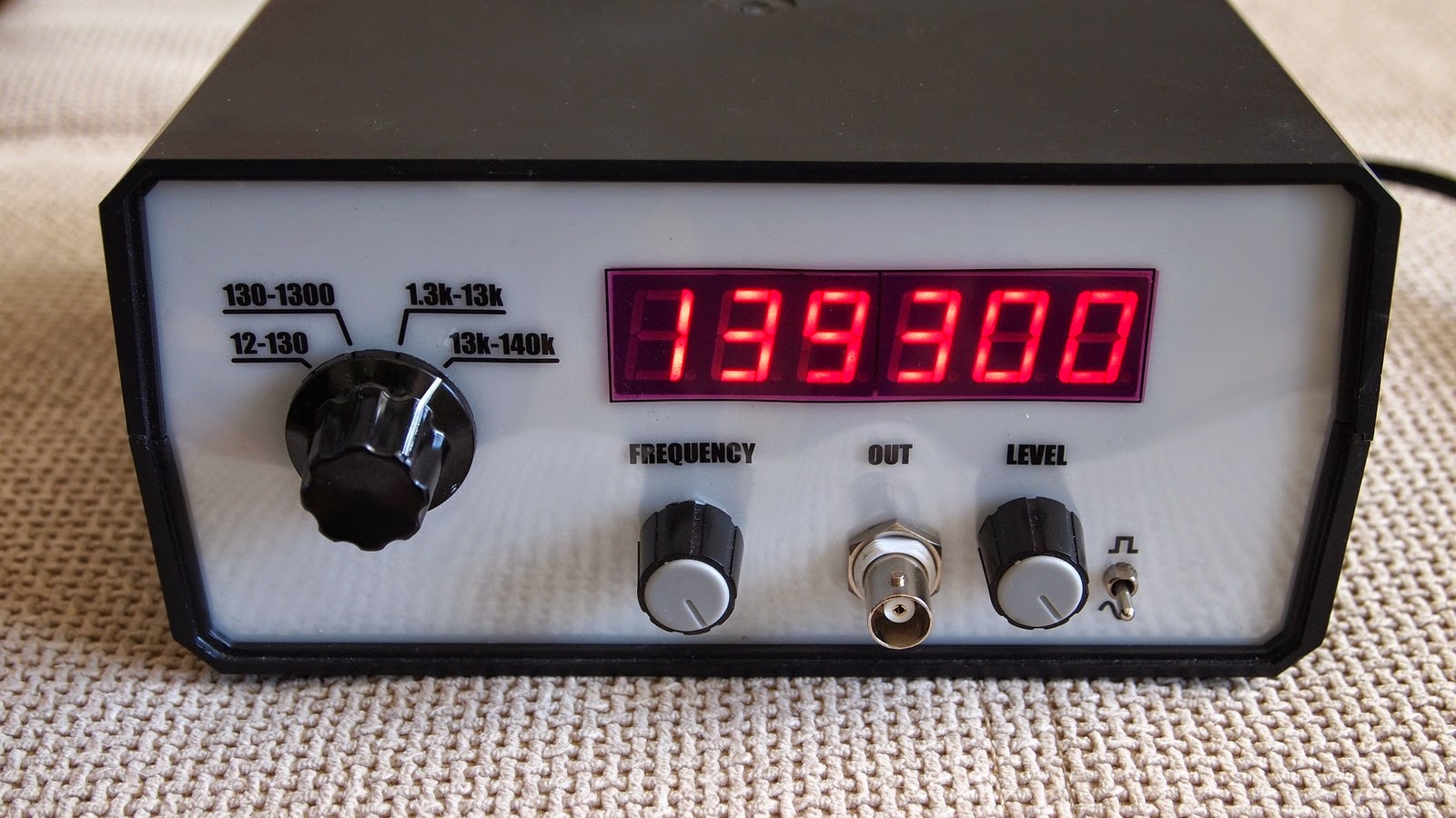
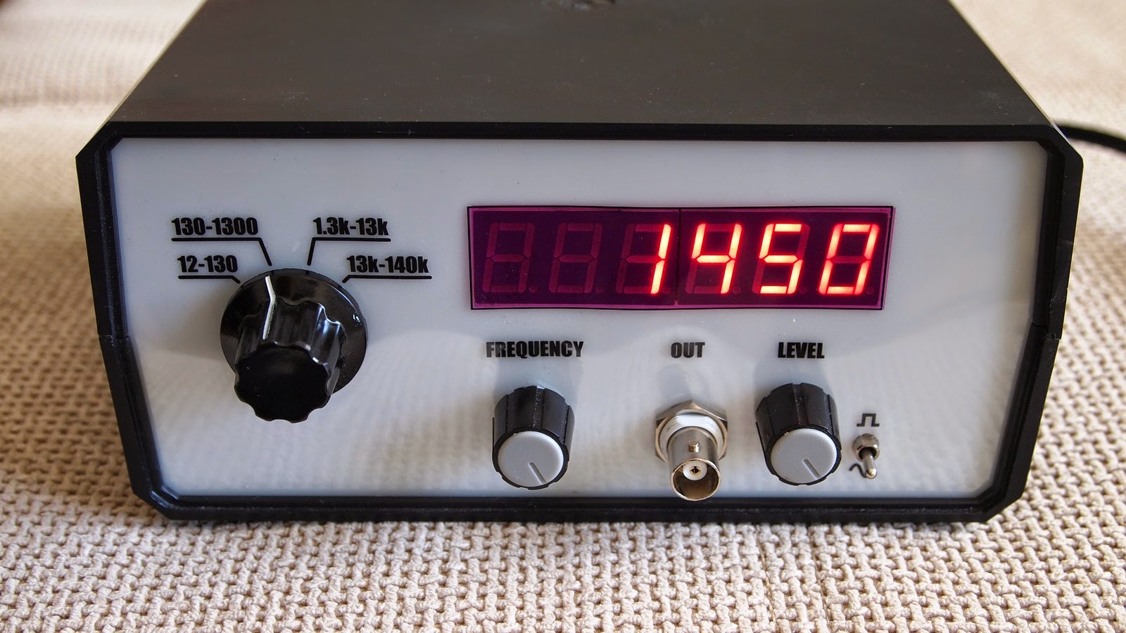
As you can see, the position of the BNC connector and two knobs is not very convenient. In the last revision of the PCB I switched the positions of the BNC connector and the LEVEL potentiometer.
All in all I am satisfied with the result.
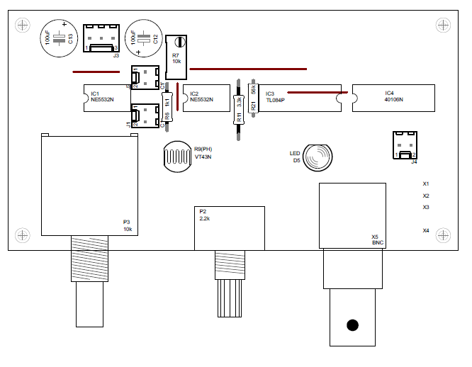
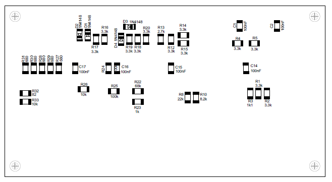
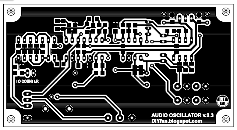
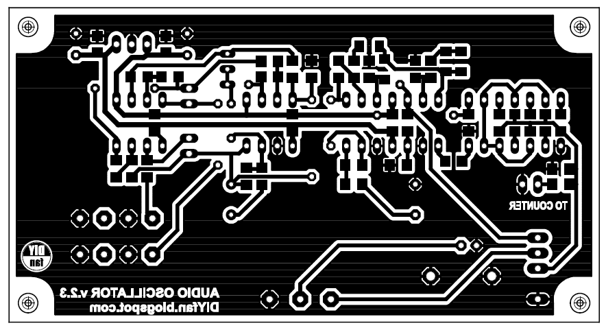
PCB


 Audio Power Amplifier")
