

Color Detector Using TCS230 Color sensor and Arduino
- Nick Koumaris
- http://educ8s.tv
- info@educ8s.tv
- 18.940 Views
- moderate
- Tested
- 0 Likes

Hi guys, welcome to today’s tutorial. In this tutorial we will look at how to use the TCS230 color sensor with Arduino. To demonstrate the ability of the color sensor, we will build a color detector system capable of detecting the color in front of the sensor and displaying that color on a TFT Display. For this project, we will use the TCS230 color sensor and the color will be displayed on the ST7735 1.8″ TFT Display.
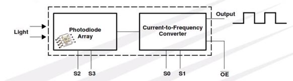
The TCS230 is a programmable color light-to-frequency converter which combines configurable silicon photodiodes and a current-to-frequency converter on a single monolithic CMOS integrated circuit.
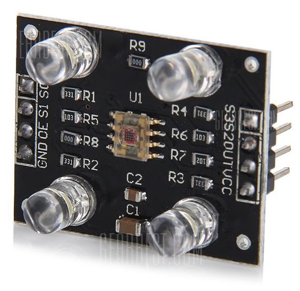
The color sensor module is made up of the color sensor itself and four Infrared LEDs which are used to illuminate any object placed in front of the sensor to ensure the readings are accurate and are not affected by the surrounding illumination. The sensor is made up of an array of photodiodes with color filters for red, blue, green and a clear filter on top.
The detect a color, the sensor reads an 8×8 array of photodiodes which comprises of 16 photodiodes with blue filters, 16 photodiodes with green filters, 16 photodiodes with red filters, and 16 photodiodes are clear with no filters. The four types (colors) of photodiodes are interdigitated to minimize the effect of non-uniformity of incident irradiance. All 16 photodiodes of the same color are connected in parallel and which type of photodiode the device uses during operation is pin-selectable.
The output of the TCs230 color sensor is a 50% duty cycle square wave whose frequency is proportional to the light intensity of the selected filter.
Required Components
The following components are required to build this project;
As usual, these components can be bought through the link attached to them.
Schematics
Connect the TCS230 and the TFT Display to the Arduino as shown in the schematics below.
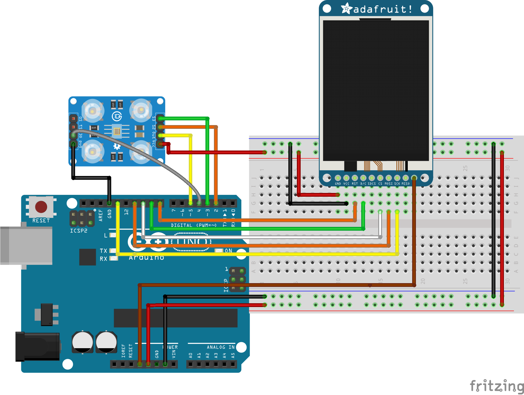
The pin connections between the Color sensor and the TFT with the Arduino is described below:
ST7735 – Arduino
LED - 3.3V
SCK - D13
SDA - D11
DC - D9
CS - D10
Reset - D8
GND - GND
VCC - 5V
TCS230 – Arduino
VCC - 5V
GND - GND
Out - D5
S2 - D2
S3 - D3
OE - D4
Some TCS230 modules include a LED Pin, if this is the model you have, you should connect the LED pin to the 5V pin of the Arduino.
More information on how to connect and use the ST7735 TFT display has been covered in a previous tutorial here and it may help you understand how the display works.
Go over the schematics once again to ensure everything is rightly connected before moving to the next section.
Code
To easily write the code for this project we need four libraries, two of which are needed to enable us to interface with the color sensor and extract readings while the other two are needed to enable us to use the TFT display. The required libraries are:
The libraries can be downloaded via the links attached to each of them.
With the libraries installed, we can then proceed to write the code for the project.
The first thing we do is to include the libraries that will be used, which in this case are the libraries mentioned above.
 //////////////////////////////////////////////
  //       Arduino Color Sensor Tutorial      //
 //          with ST7735 TFT LCD             //
//           http://www.educ8s.tv           //
/////////////////////////////////////////////

#include <MD_TCS230.h>
#include <FreqCount.h>
#include <Adafruit_ST7735.h>
#include <Adafruit_GFX.h>
Next, we declare the pins of the Arduino to which the CS, DC and RST pins of our display are connected to.
#define cs   10
#define dc   9
#define rst  8
Next, we declare the colors specifying their hex values and we also declare the GPIO pins of the Arduino to which the color sensor pins are connected.
// Color definitions
#define BLACK    0x0000
#define BLUE     0x001F
#define RED      0xF800
#define GREEN    0x07E0
#define CYAN     0x07FF
#define MAGENTA  0xF81F
#define YELLOW   0xFFE0
#define WHITE    0xFFFF
#define GREY     0xC618

// Pin definitions
#define  S2_OUT  2
#define  S3_OUT  3
#define  OE_OUT   4    // LOW = ENABLED
Next, we create three variables to represent red(R), green(G) and blue(B). These variables will capture the color content of the data received by the color sensor.
int R = 0;
int G = 0;
int B = 0;
Next, we create an instance of the Color sensor library and the ST7735 display’s library specifying the required pins.
MD_TCS230 CS(S2_OUT, S3_OUT, OE_OUT);

int state = 0;

Adafruit_ST7735 tft = Adafruit_ST7735(cs, dc, rst);
With all the preliminary jobs done, we then move to the void setup() function, where we initialize the display and display a welcome text. We then start communication with the color sensor.
void setup() {

  Serial.begin(57600);

  tft.initR(INITR_BLACKTAB);   // initialize a ST7735S chip, black tab

  drawBlackScreen();

  tft.setCursor(20,30);
  tft.setTextColor(RED);
  tft.setTextSize(2);
  tft.print("Color");

  tft.setCursor(20,60);
  tft.setTextColor(GREEN);
  tft.setTextSize(2);
  tft.print("Sensor");

  tft.setCursor(20,90);
  tft.setTextColor(BLUE);
  tft.setTextSize(2);
  tft.print("Tutorial");

  delay(3000);

  drawBlackScreen();

   tft.setCursor(10,30);
   tft.setTextColor(WHITE);
   tft.setTextSize(2);
   tft.print("SET BLACK");
   delay(5000);

   CS.begin();
   CS.read();
}
Next up is the void loop function. The first thing we do under this function is to calibrate the color sensor by feeding it Black and white colors, once our project recognizes these colors, it’s then calibrated and able to recognize any other color in between.
void loop() {

if(state ==0)
{
  if (CS.available()) {
   sensorData  sd;
   CS.getRaw(&sd);
   CS.setDarkCal(&sd);
   Serial.println("Black Calibration Set");
   state++;
   drawBlackScreen();

   tft.setCursor(10,30);
   tft.setTextColor(WHITE);
   tft.setTextSize(2);
   tft.print("SET WHITE");

   delay(5000);
   CS.read();
  }
}
After the calibration has been done, the state variable becomes greater than zero and the program starts running. From this point the module can read any color fed to it.
void loop() {

if(state ==0)
{
  if (CS.available()) {
   sensorData  sd;
   CS.getRaw(&sd);
   CS.setDarkCal(&sd);
   Serial.println("Black Calibration Set");
   state++;
   drawBlackScreen();

   tft.setCursor(10,30);
   tft.setTextColor(WHITE);
   tft.setTextSize(2);
   tft.print("SET WHITE");

   delay(5000);
   CS.read();
  }
}
The complete code for this project is available below and also included in the zip file under the download section.
   //////////////////////////////////////////////
  //       Arduino Color Sensor Tutorial      //
 //          with ST7735 TFT LCD             //
//           http://www.educ8s.tv           //
/////////////////////////////////////////////

#include <MD_TCS230.h>
#include <FreqCount.h>
#include <Adafruit_ST7735.h>
#include <Adafruit_GFX.h>

#define cs   10
#define dc   9
#define rst  8

// Color definitions
#define BLACK    0x0000
#define BLUE     0x001F
#define RED      0xF800
#define GREEN    0x07E0
#define CYAN     0x07FF
#define MAGENTA  0xF81F
#define YELLOW   0xFFE0
#define WHITE    0xFFFF
#define GREY     0xC618

// Pin definitions
#define  S2_OUT  2
#define  S3_OUT  3
#define  OE_OUT   4    // LOW = ENABLED

int R = 0;
int G = 0;
int B = 0;

MD_TCS230 CS(S2_OUT, S3_OUT, OE_OUT);

int state = 0;

Adafruit_ST7735 tft = Adafruit_ST7735(cs, dc, rst);

void setup() {

  Serial.begin(57600);

  tft.initR(INITR_BLACKTAB);   // initialize a ST7735S chip, black tab

  drawBlackScreen();

  tft.setCursor(20,30);
  tft.setTextColor(RED);
  tft.setTextSize(2);
  tft.print("Color");

  tft.setCursor(20,60);
  tft.setTextColor(GREEN);
  tft.setTextSize(2);
  tft.print("Sensor");

  tft.setCursor(20,90);
  tft.setTextColor(BLUE);
  tft.setTextSize(2);
  tft.print("Tutorial");

  delay(3000);

  drawBlackScreen();

   tft.setCursor(10,30);
   tft.setTextColor(WHITE);
   tft.setTextSize(2);
   tft.print("SET BLACK");
   delay(5000);

   CS.begin();
   CS.read();
}

void loop() {

if(state ==0)
{
  if (CS.available()) {
   sensorData  sd;
   CS.getRaw(&sd);
   CS.setDarkCal(&sd);
   Serial.println("Black Calibration Set");
   state++;
   drawBlackScreen();

   tft.setCursor(10,30);
   tft.setTextColor(WHITE);
   tft.setTextSize(2);
   tft.print("SET WHITE");

   delay(5000);
   CS.read();
  }
}
else if(state == 1)
{
 if (CS.available()) {
   sensorData  sd;
   CS.getRaw(&sd);
   CS.setWhiteCal(&sd);
   Serial.println("White Calibration Set");
   drawBlackScreen();

   tft.setCursor(35,30);
   tft.setTextColor(WHITE);
   tft.setTextSize(2);
   tft.print("COLOR");
   tft.drawRect(30,70,70,60,WHITE);
   state++;
  }

}else
{
  readSensor();
}


}

void drawBlackScreen()
{
  tft.fillScreen(BLACK);
  //Draw white frame
  tft.drawRect(0,0,127,159,WHITE);
  tft.drawRect(1,1,127,159,WHITE);
}

uint16_t convertRGB24toRGB565(uint8_t r, uint8_t g, uint8_t b)
{
  return ((r / 8) << 11) | ((g / 4) << 5) | (b / 8);
}

void readSensor()
{
  static  bool  waiting = false;

  if (!waiting)
  {
    CS.read();
    waiting = true;
  }
  else
  {
    if (CS.available())
    {
      colorData  rgb;

      CS.getRGB(&rgb);
      Serial.print("RGB [");
      Serial.print(rgb.value[TCS230_RGB_R]);
      Serial.print(",");
      Serial.print(rgb.value[TCS230_RGB_G]);
      Serial.print(",");
      Serial.print(rgb.value[TCS230_RGB_B]);
      Serial.println("]");

      R = rgb.value[TCS230_RGB_R];
      G = rgb.value[TCS230_RGB_G];
      B = rgb.value[TCS230_RGB_B];

      int color = convertRGB24toRGB565(R,G,B); //Convertion to 16bit color for the display

      delay(100);

      tft.fillRect(31,71,68,58,color);

      waiting = false;
    }
  }
}
Demo
Check your connections once more to be sure everything is correct, then upload the code to the Arduino and put colored paper or any colored material in front of the color sensor. Don’t forget to calibrate the sensor using black and white colors first before feeding it other colors. The image below shows the project recognizing the yellow color.
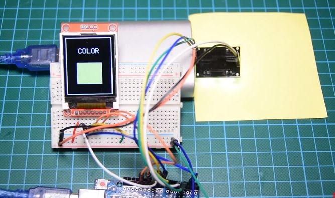
Cool right?
That’s it for this tutorial guys, color sorting has several real-life applications and I’m sure it is awesome to know that this can be done with something as cheap as the Arduino. What problem will you solve with this tutorial, let’s get the conversation started. Feel free to reach me via the comment section if you have any questions in regards to the tutorial.
Till next time!
You can watch the video of this tutorial on youtube here


in this code draw blackscreen () function defination is not there