

DC Motor Speed and Direction Controller using L293D
- Rajkumar Sharma
- 26.463 Views
- moderate
- Tested
- SKU: EL47951
- Quote Now
- 0 Likes

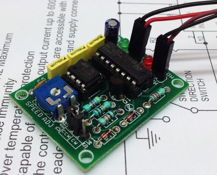
DC Motor Speed and direction controller project based on L293D H-Bridge and 555 Timer IC. 555 Generate PWM and L293D works as output driver. The 293D provides bidirectional drive current up to 600mA a voltage from 5V to 12V. L293D includes the output clamping diodes for protections.
Specifications
- Supply 5 to 12 V
- Inhibit facility/enable
- PWM Frequency 5KHz Maximum
- High Noise immunity
- Over temperature protection
- Capable of delivering output current up to 600 mA per channel
- The control/interface lines are accessible with Berg connector
- Header connector for motor and supply connection
- PR1 : Preset Speed Adjust
- SW1 : 3Pin Jumper and Closer for Direction change
- CN1 : DC Motor Supply input 5V to 12V DC
- Dimensions 48.26mm x 36.83mm
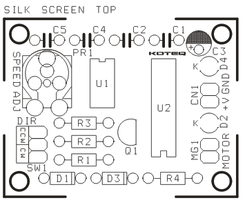
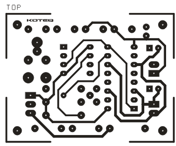
Schematic

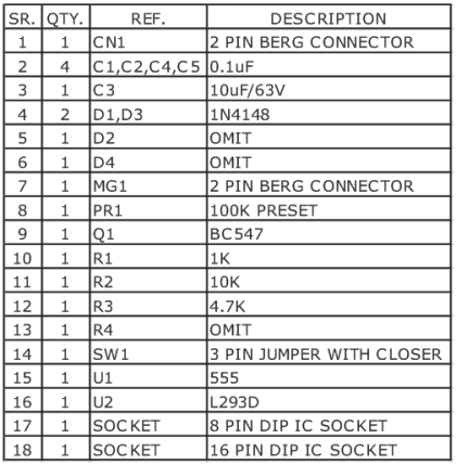
Parts List
Photos

Video
Please follow and like us:
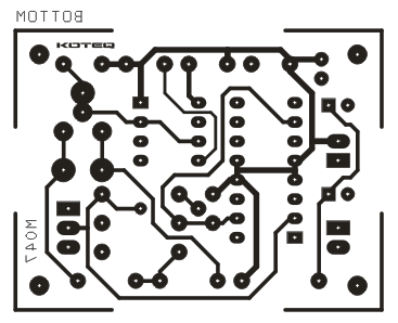
PCB


dimensions?
Dimensions 48.26mmX36.83mm
Plz give to working for this project
I remember making this circuit as far is the 555 is concerned which was driving a MOSFET eventually driving the motor but the problem was even at minimum speed there was a whine from the motor and my scope showed that there was a needle pulse flowing into the FET and inturn into the motor, so essentially this basic circuit of the 555 does not give a zero to 100% modulation resulting in an annoying noticeable whine which was further evident when i wired an led across the motor showing the distinct thin pulses.