
DIY Light (Lux) Meter using BH1750 sensor, Arduino and Nokia 5110
- Nick Koumaris
- http://educ8s.tv
- info@educ8s.tv
- 16.186 Views
- moderate
- Tested
- 0 Likes

Introduction
Hi guys, continuing on our recent path of building really cool stuffs based on the Nokia 5110 LCD display, today we will be building a DIY Lux (or light) meter using the highly sensitive BH1750 light sensor.
Illuminance (measured in LUX) is the total luminous flux incident on a surface, per unit area. It is a measure of how much the incident light illuminates the surface, it is wavelength-weighted by the luminosity function to correlate with the level of human brightness perception.
Lux is a measurement of the overall intensity of light within an environment for any given area or distance from the source or lux is the amount of light in an environment perceived by the human eye. The Lux meter is thus, a device used to measure the light intensity within an environment and its exactly what we will be building during this tutorial.
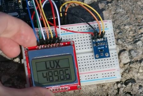
Below is a picture of the device taking outdoor readings on a bright morning.
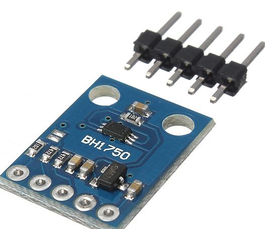
The BH1750 sensor is a digital Light Sensor capable of measuring light intensity with a great degree of accuracy and over a large range. It communicates with microcontrollers or processors to which it is connected via the I2C bus interface. This module is the most suitable to obtain the ambient light data and it is commonly used for adjusting LCD and Keypad backlight power of Mobile phones.
Some of the features of this sensor include;
- I2C bus Interface ( f / s Mode Support )
- Spectral responsibility is approximately human eye response
- Illuminance to Digital Converter
- Wide range and High resolution. ( 1 – 65535 lx )
- Low Current by power down function
- 50Hz / 60Hz Light noise reject-function
- It is possible to select 2 type of I2C slave-address.
- Adjustable measurement result for influence of optical window ( It is possible to detect min. 0.11 lx, max. 100000 lx by using this function. )
- Small measurement variation (+/- 20%)
Required Components
The following components are needed to build this project;
Schematics
Connect all components as shown in the Fritzing schematics below;
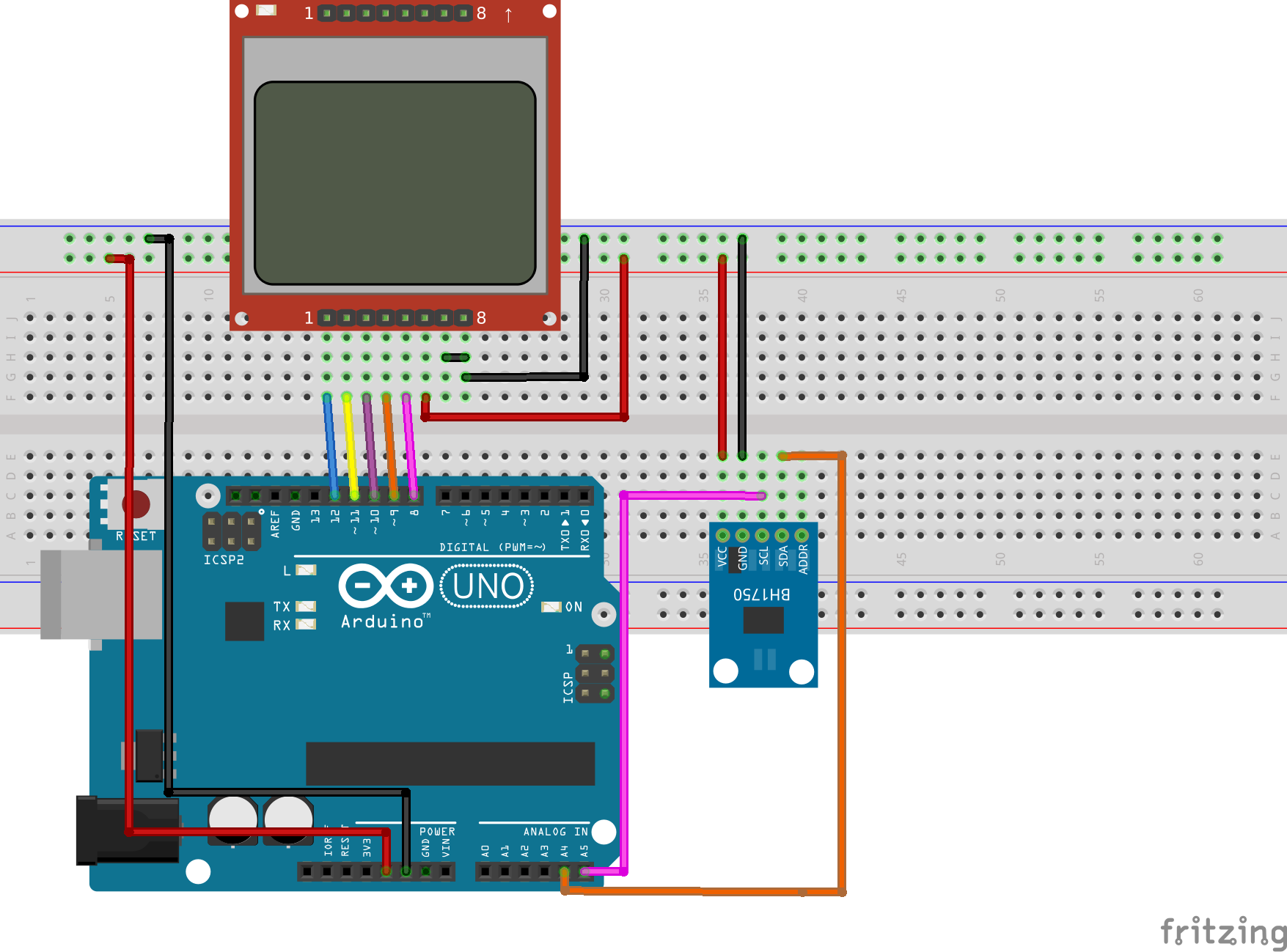
The BH1750 light intensity sensor module has a 16-bit analog to digital converter built-in that can directly output a digital signal over I2C communication protocol, thus the device is connected to the Arduino I2C pins which are located on analog pin 4(SDA) and 5(SCL). The connection is further detailed below.
BH1750 – Arduino
vcc - 5v
GND - GND
SCL - A5
SDA - A4
For the Nokia 5110 LCD module, a detailed tutorial has been made before on how to use the module with the Arduino and can be found here. It will help you better understand how the Nokia 5110 connection with the Arduino works. For this project, however, the pin connection of the Nokia 5110 LCD to the Arduino (as shown in the schematics) is given below;
LCD – ARDUINO
Pin 1(RST) – D12
Pin 2(CE) – D11
Pin 3(DC) – D10
Pin 4(DIN) – D9
Pin 5(CLK) – D8
Pin 6(VCC) - VCC
Pin 7(LIGHT) - GND
Pin 8(GND) - GND
Double check your connections to be sure you got everything right before proceeding to the code.
Code
Like most of our projects, In order to easily program our arduino to work with the BH1750 light sensor, we need the BH1750 arduino library. For this tutorial we will be using the library which can be found here. Download the library, and install in your arduino IDE by unzipping and copying it to the arduino library folder.
Since we are using the Nokia 5110 LCD display, we will also need the library which can be downloaded from here and installed in the same way as the BH1750 library. To know more about the Nokia 5110 LCD, check out the tutorial on it which can be found above.
With our libraries all installed, we are ready to launch the Arduino IDE and get to work.
The code file for this project, attached in the zip file at the end of this tutorial, contains three files; the Arduino code, the hex file for the graphics displayed on the screen when the device is powered and the UI design for the display. A detailed tutorial on how to prepare graphics and load them on to the Nokia 5110 LCD is found here, It will be of immense help when it comes to understanding how to load graphics to the display.
The first thing we do in our code includes the libraries that we will be using, which are the BH1750 library, the Nokia 5110 LCD library and the Arduino Wire LIbrary which is needed for the I2C communication.
//Written by Nick Koumaris
//info@educ8s.tv
//educ8s.tv

#include <LCD5110_Graph.h>
#include <Wire.h>
#include <BH1750.h>
Next we declare the pins to which the lcd is connected to, and also specify the font tupe and the name of the graphics and ui files.
LCD5110 lcd(8,9,10,12,11);
extern unsigned char BigNumbers[];
extern uint8_t splash[];
extern uint8_t ui[];
Next, we create an object of BH1750 and also declare the string variable which will hole all the light information from the sensor.
BH1750 lightSensor;
String light;
With this done, we are then ready to move to the setup function, the commands under this section seem quite easy to grab to me. I2C communication system is started, followed by initializing the LCD, font settings, and the display of the splash screen icon. The system waits for a couple of seconds before proceeding to the loop section to give the splash screen enough time on the display.
void setup() {

 lightSensor.begin();
 lcd.InitLCD();
 lcd.setFont(BigNumbers);
 lcd.clrScr();
 lcd.drawBitmap(0, 0, splash, 84, 48);
 lcd.update();
 delay(3000);

}
With the setup function all done, we are now ready to proceed to the loop function.
The loop function is pretty basic. the first command initializes the string length setting it to 0. The next command reads the light intensity reading from the sensor then the screen is cleared, the UI uploaded to the screen and the sensor data is printed to the screen after conversion.
A delay is set to allow the function to take some time in between readings.
void loop() {

 int stringLength=0;

 uint16_t lux = lightSensor.readLightLevel();

 light = String(lux);
 stringLength = light.length();

 lcd.clrScr();
 lcd.drawBitmap(0, 0, ui, 84, 48);
 printLight(stringLength);
 lcd.update();

 delay(150);
}
The Last block of code is the function which was used to print the string data.
void printLight(int length)
{
  switch(length)
  {
    case 1:  lcd.print(light,68,22); break;
    case 2:  lcd.print(light,54,22); break;
    case 3:  lcd.print(light,40,22); break;
    case 4:  lcd.print(light,26,22); break;
    case 5:  lcd.print(light,12,22); break;
    default:  lcd.print(light,0,22); break;
  }
}
The full code is available below and also in the attached zip file.
#include <LCD5110_Graph.h>
#include <Wire.h>
#include <BH1750.h>

LCD5110 lcd(8,9,10,12,11);
extern unsigned char BigNumbers[];
extern uint8_t splash[];
extern uint8_t ui[];

BH1750 lightSensor;
String light;

void setup() {

 lightSensor.begin();
 lcd.InitLCD();
 lcd.setFont(BigNumbers);
 lcd.clrScr();
 lcd.drawBitmap(0, 0, splash, 84, 48);
 lcd.update();
 delay(3000);

}

void loop() {

 int stringLength=0;

 uint16_t lux = lightSensor.readLightLevel();

 light = String(lux);
 stringLength = light.length();

 lcd.clrScr();
 lcd.drawBitmap(0, 0, ui, 84, 48);
 printLight(stringLength);
 lcd.update();

 delay(150);
}

void printLight(int length)
{
  switch(length)
  {
    case 1:  lcd.print(light,68,22); break;
    case 2:  lcd.print(light,54,22); break;
    case 3:  lcd.print(light,40,22); break;
    case 4:  lcd.print(light,26,22); break;
    case 5:  lcd.print(light,12,22); break;
    default:  lcd.print(light,0,22); break;
  }
}
Feel free to copy and paste in the Arduino IDE once setups like library installation etc are done.
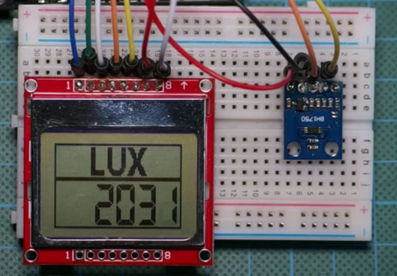
Demo
Copy the code, paste in the Arduino IDE, and upload to your arduino board, you should get an output like the image below on your screen. Don’t forget to include the icon file in the Arduino sketch folder.
That’s it for this tutorial guys. As usual, let me know if you have any questions via the comments section.
The youtube video of this tutorial is available here.


