

DS18B20 Sensor Based Thermometer with Nokia 5110 LCD display
- Nick Koumaris
- http://educ8s.tv/
- info@educ8s.tv
- 8.862 Views
- moderate
- Tested
- 0 Likes

Hi guys welcome to this tutorial. Today we will be building a simple temperature monitor using the DS18B20 sensor with a Nokia 5110 LCD Display and an Arduino mega.
Introduction
The DS18B20 digital temperature sensor gives a 9-bit to 12-bit Celsius temperature readings and also has an alarm function with nonvolatile user-programmable upper and lower trigger points. The sensor communicates via the 1-Wire communication protocol and thus by definition requires only one data line (and ground) for communication with a central microprocessor. Among the special features of this sensor, is an operational mode in which it can derive power directly from the data line (“parasite power”), eliminating the need for an external power supply line.

Each DS18B20 has a unique 64-bit serial code, which allows multiple DS18B20s to work on the same 1-Wire bus. Thus, it is simple to use one micro-controller to control many DS18B20s distributed over a large area. Some applications that can benefit from this capability include HVAC systems, temperature monitoring systems inside buildings, equipment, or machines, and process monitoring and control systems.
The Nokia 5110 was used to provide a feedback on the temperature values to the user but the Arduino serial monitor may also be used for those who do not have the display and the code for this is also included.
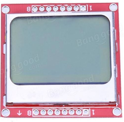
A more detailed tutorial on using the Nokia 5110 LCD display can be found here.
Required Components
The following components with links attached to where they can be bought are needed for this project:
Schematics
Connect all the components as shown in the schematics below.
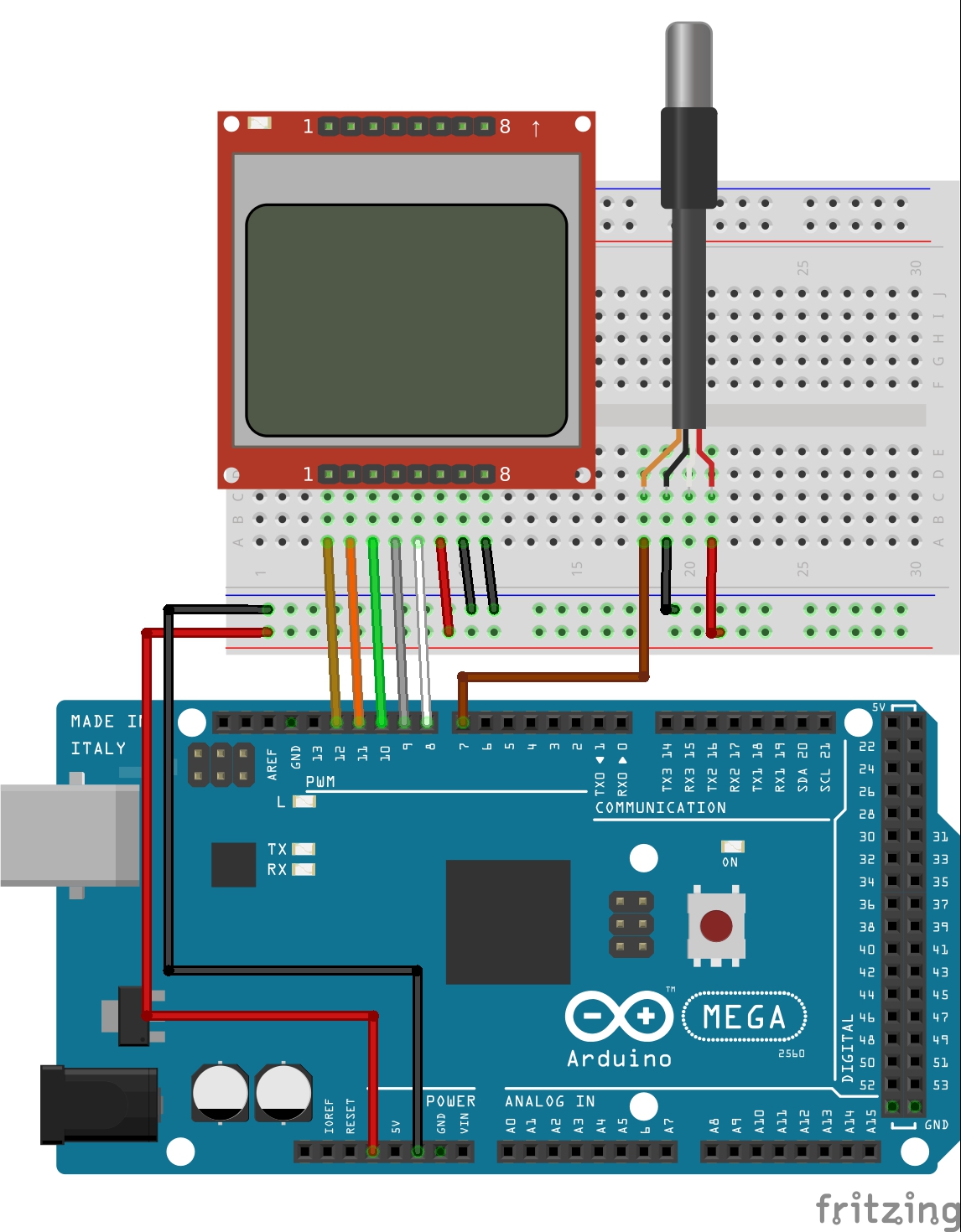
For clarity, the pin connections are also described below.
DS18b20 – Arduino Mega
VCC - 3.3v
GND - GND
SIG - D7

The other part of the schematic is only needed by those who have the Nokia 5110 display.
Nokia 5110 – Arduino
Display - Arduino
Pin 1(RST) – D12
Pin 2(CE) – D11
Pin 3(DC) – D10
Pin 4(DIN) – D9
Pin 5(CLK) – D8
Pin 6(VCC) - VCC
Pin 7(LIGHT) - GND
Pin 8(GND) - GND
Code
In order to use this sensor, we need to download three libraries;
- One-Wire Arduino Library
- Arduino Temperature control library
- Nokia 5110 LCD Library (This is only needed if you will be using the LCD)
The first library is the one-wire Arduino library. The one-wire Arduino Library allows one-wire enabled devices to communicate over the one-wire protocol with Arduino microcontrollers. On the 1-wire network which is also referred to as a “MicroLan” (trademark), a single “master” device communicates with one or more 1-Wire “slave” devices over a single data line, with an added perk of the same data line serving as power line for the sensor in a mode known as “parasitic” Mode. This means that we can connect multiple DS18B20 temperature sensor on the same Arduino pin (saving a whole lot of IOs).
The second library we will need is the Miles Burton Arduino temperature control library.
The Arduino temperature control library was created to make it easy to get temperature information from the Maxim Integrated temperature sensor.
Install these libraries with the Arduino by unzipping and copying to the location on your PC location where you have the Arduino libraries.
With this done, we are then ready to program our Arduino to read the temperature sensor.
We will be making two codes available for this project;
- SerialTemperature.ino
- TemperatureNokia5110.ino
The first one (SerialTemperature.ino) displays the data over the Arduino serial monitor so that people who do not have the Nokia 5110 LCD display can also follow the tutorial by viewing the temperature data via the serial communication port.
The second code (TemperatureNokia5110.ino) is for those who have the Nokia 5110 lcd display.
Each of the codes will be explained differently to cover all the angles involved.
Let’s start with the first one.
Serial Temperature
The first thing we do is include the libraries we downloaded earlier.
//Written by Nick Koumaris
//Info@educ8s.tv
//educ8s.tv
#include <OneWire.h>
#include <DallasTemperature.h>
Next, we declare the pin to which our temperature sensor’s signal pin is connected, after which, the one wire method is called.
#define ONE_WIRE_BUS 7

OneWire oneWire(ONE_WIRE_BUS);
Next we need to declare the variables for holding the temperatures both in farenheit(TempF) and in degrees(TempC).
With this done, we then move to the setup function and startup the serial monitor with 9600 as the baud rate and also issue the command sensors.begin, which starts up communication with the temperature sensor via 1-wire.
float tempC = 0;
float tempF = 0;

void setup(void)
{
  Serial.begin(9600);
  sensors.begin();
}
Next we go into the void loop function. The void loop function contains three main lines. The first line reads the temperature from the temperature sensor. using the sensor.requestTemperatures() function. After this, the temperature in degrees Celsius is acquired using the second line. The index “0” is what needs to be changed to either 1 or 2 or N when you have multiple sensors on the 1-wire line.
With the temperature in Celsius gotten, the next line of code then obtains the temperature in Fahrenheit and its all then formatted to be nicely displayed by the printTemperature() function.
void loop(void)
{

  sensors.requestTemperatures();
  tempC = sensors.getTempCByIndex(0);
  tempF = sensors.toFahrenheit(tempC);

  printTemperature();

  delay(1000);
}
The remaining part of the code represents the print temperature function.
void printTemperature()
{
  Serial.print(tempC);
  Serial.print(char(176));
  Serial.print("C");
  Serial.print("\t");
  Serial.print(tempF);
  Serial.print(char(176));
  Serial.print("F");
  Serial.print("\n");
}
So for those without the Nokia 5110 LCD, here is the full code.
//written by Nick Koumaris
//info@educ8s.tv
//educ8s.tv

#include <OneWire.h>
#include <DallasTemperature.h>

#define ONE_WIRE_BUS 7

OneWire oneWire(ONE_WIRE_BUS);

DallasTemperature sensors(&oneWire);

float tempC = 0;
float tempF = 0;

void setup(void)
{
  Serial.begin(9600);
  sensors.begin();
}

void loop(void)
{

  sensors.requestTemperatures();
  tempC = sensors.getTempCByIndex(0);
  tempF = sensors.toFahrenheit(tempC);

  printTemperature();

  delay(1000);
}

void printTemperature()
{
  Serial.print(tempC);
  Serial.print(char(176));
  Serial.print("C");
  Serial.print("\t");
  Serial.print(tempF);
  Serial.print(char(176));
  Serial.print("F");
  Serial.print("\n");
}
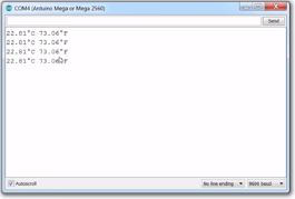
Copy, paste in the Arduino IDE and upload to your board. You should see outputs on your serial monitor like the image below.
All done, it is time to take a look at the code for those who have the Nokia 5110 LCD display.
Temperature with Nokia 5110 LCD Code
There are two sides to the code for this. The first one is the temperatureIcon.c file which is essentially the binary data representing the Icon that was used on the LCD.
The second file is the TemperatureNokia5110.ino file which contains the actual arduino code which I am about to explain.
Just like for the serial version of this code, we import the necessary libraries. In this case, we have to add the LCD library.
//Written by Nick Koumaris
//info@educ8s.tv
//Educ8s.tv
#include <OneWire.h>
#include <DallasTemperature.h>
#include <LCD5110_Graph.h>
with this done, a 1-wire object is created and other variable declarations needed for both the screen and the sensor are handled.
#define ONE_WIRE_BUS 7

LCD5110 lcd(8,9,10,12,11);

extern unsigned char SmallFont[];
extern unsigned char BigNumbers[];
extern uint8_t temperatureIcon[];

char temperatureF[6];

OneWire oneWire(ONE_WIRE_BUS);

DallasTemperature sensors(&oneWire);

float tempC = 0;
float tempF = 0;
With this done, we then proceed to the setup function where we, initialized the LCD, set its display font and then start communication with the sensor.
void setup(void)
{
  lcd.InitLCD();
  lcd.setFont(BigNumbers);
  sensors.begin();
}
Setup all done? we then move to the Loop section. The first function in the loop section clears the LCD screen, after which the Icon is drawn using the draw bitmap function. After the bitmap is drawn, then the all familiar functions to read the temperature both in Celsius and Farenheit and display on the LCD.
void loop(void)
{

  lcd.clrScr();
  lcd.drawBitmap(0, 0, temperatureIcon, 84, 48);

  sensors.requestTemperatures();

  tempC = sensors.getTempCByIndex(0);
  tempF = sensors.toFahrenheit(tempC);

  convertToString(tempF);

  //convertToString(tempC);  //Uncomment this for degrees Celsius

  lcd.print(temperatureF,25,11);

  lcd.update();
  delay(1000);
}
The last part of the code is the function to convert readings to string.
void convertToString(float number)
{
   dtostrf(number, 3, 1, temperatureF);
}
The full code for this route is available below, and also available for download at the end of the tutorial page.
//Written By Nick koumaris
//info@educ8s.tv
//educ8s.tv

#include <OneWire.h>
#include <DallasTemperature.h>
#include <LCD5110_Graph.h>

#define ONE_WIRE_BUS 7

LCD5110 lcd(8,9,10,12,11);

extern unsigned char SmallFont[];
extern unsigned char BigNumbers[];
extern uint8_t temperatureIcon[];

char temperatureF[6];

OneWire oneWire(ONE_WIRE_BUS);

DallasTemperature sensors(&oneWire);

float tempC = 0;
float tempF = 0;

void setup(void)
{
  lcd.InitLCD();
  lcd.setFont(BigNumbers);
  sensors.begin();
}

void loop(void)
{

  lcd.clrScr();
  lcd.drawBitmap(0, 0, temperatureIcon, 84, 48);

  sensors.requestTemperatures();

  tempC = sensors.getTempCByIndex(0);
  tempF = sensors.toFahrenheit(tempC);

  convertToString(tempF);

  //convertToString(tempC);  //Uncomment this for degrees Celsius

  lcd.print(temperatureF,25,11);

  lcd.update();
  delay(1000);
}

void convertToString(float number)
{
   dtostrf(number, 3, 1, temperatureF);
}
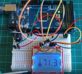
That’s it guys, you know the drill. Copy and paste in the Arduino IDE and upload to your board. You should see an output like what is in the Image below.
That’s it guys, thanks for sticking around for this one. If you have questions or comments, do drop them in the comment section and I will respond as soon as possible.
The youtube video for this tutorial can also be found here.
Till Next time.


