

Geiger counter with SBM20 tube
- j3tstream
- http://www.weirdlab.fr
- 19.717 Views
- moderate
- Non tested
- 0 Likes

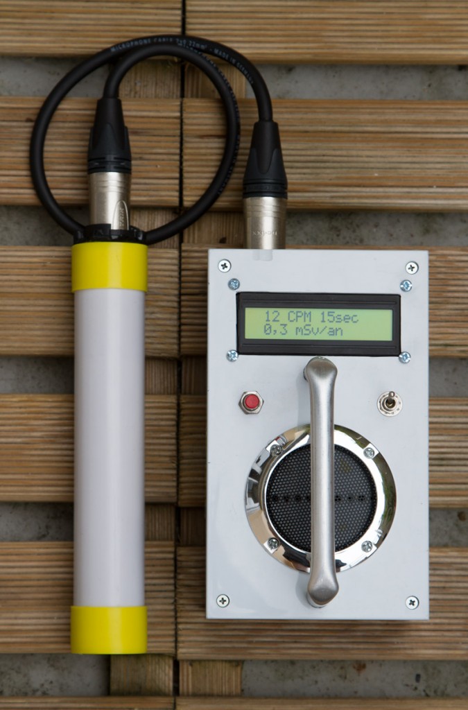
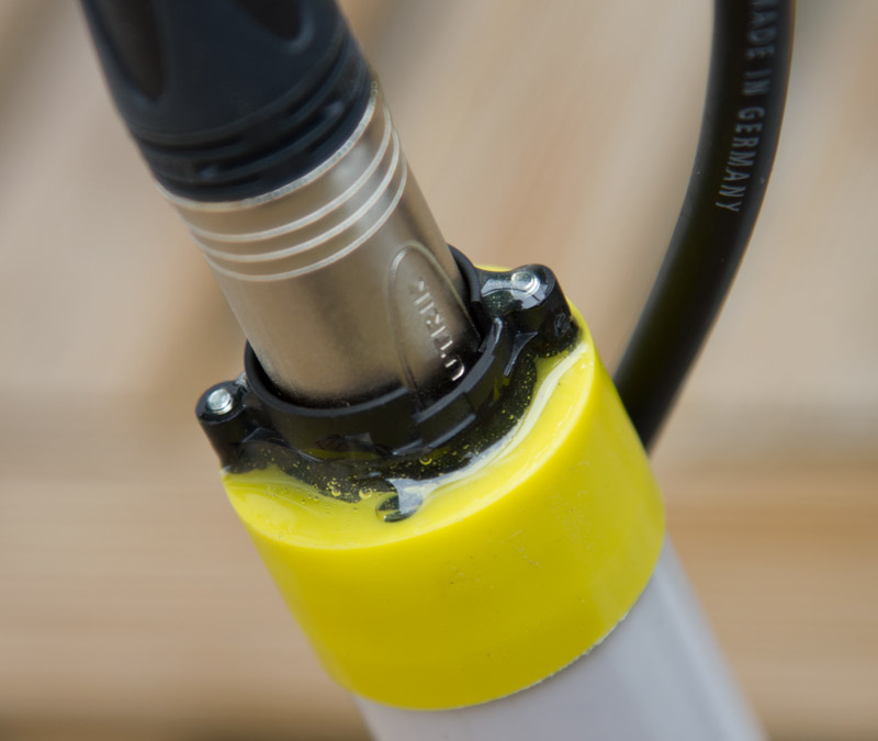
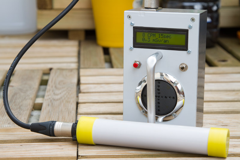
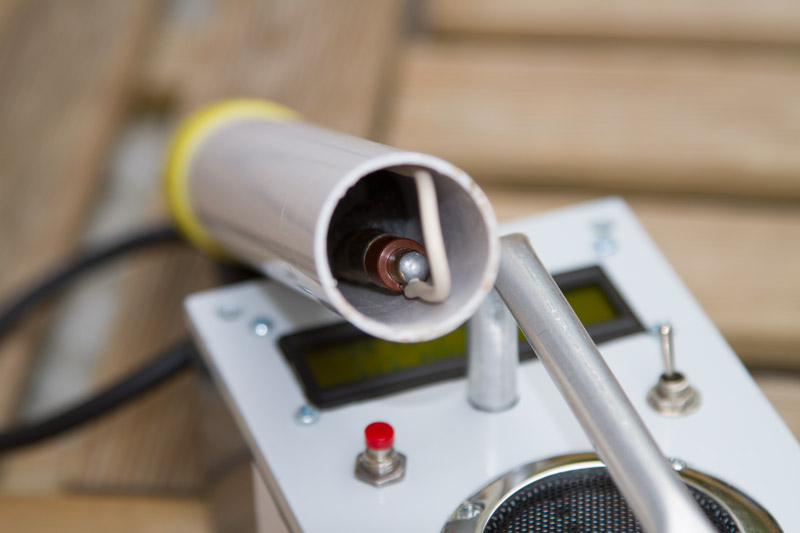
I “rebuild” my Geiger counter, the SBM-20 tube was initially inside the box, so, i have put this one inside a 32mm diam plastic tube, for more convenience, wired through a XLR3 cable.
The LCD display alternatively, the “count per minutes” and result on: milli Sievert/year or nano Sievert/hour, you can switch off/on the buzzer, also 3 modes on measure are available, 15/30/120 secs.
This counter is from “Electronique-Pratique” n°368, a French electronic magazine. Shem, pcb, and PIC hex & C source code available. (Microchip compiler C18 v2.40/MPLAB 8.4)
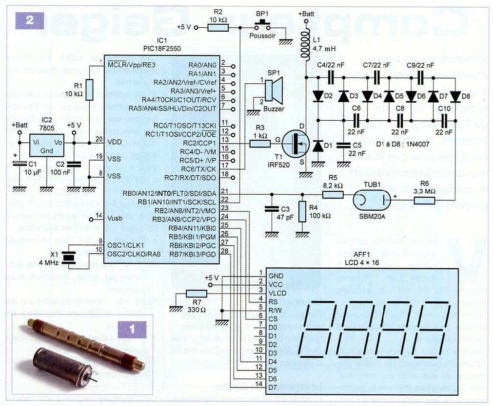
Schematic
Photos
Please follow and like us:
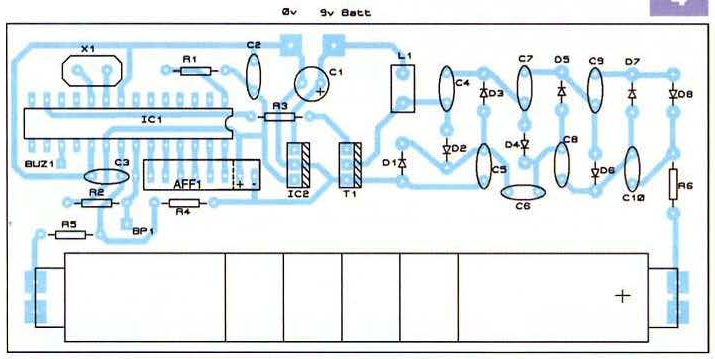
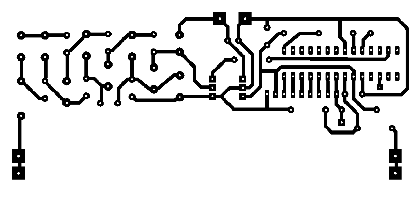
PCB


Do you have a case file drawn on this geiger counter 3d printer?
For this project a plastic or metallic case can be used. We are sorry we don’t have any 3d file for a case.
Is not the code written in the pic source file working?
According to the author the code is tested and working properly. Please be sure to program and verify your PIC microcontroller.
18f2550 is used in the circuit. 18f2455 is used in the code. Is this a problem?
The two PICs are compatible and 18F2550 has more Flash memory, so the code should work on both of them.
I saw that the diagram is given a 4×16 LCD display and on the box is a 2×16 LCD display.
I have a 2×16 LCD display, should I make a change in the software or the diagram to work with 2×16 LCD? …
Thank you.
Unfortunately, we haven’t build this project on our end and i would suggest to study the code so you can conclude how to use a 2×16 LCD display.
I’m not good at programming, maybe you help me somehow.
Thank you.
Nice! What is push button (BP1) for?
This is to select one of the 3 modes of operation.
it works very well! works very well on LCD16x2 and PIC18F2550, without modifications
This looks like an awesome project. I am definitely making one, but it doesn’t show how to connect the cable. Can anyone show how they did that or where they connected it? Thank you
The cable is just an extension of the tube’s output connections that goes to the rest of the circuit.
I understand that part of it, but the XLR3 cable has 3 wires (a positive, a negative and ground). Should the ground wire simply be bridged with the negative terminal?
This is probably obvious to most, but I am very new to building electronics and I am trying to learn. Thank you for sharing.
You can use only 2 of them, or connect negative and GND together.
I noticed that other Geiger counter circuits use atleast two types of capacitors, mylar and ceramic and possibly a third or fourth being Tantalum and/or electrolytic. I lack the knowledge of circuits to know when and where each type should be used, but I am currently reading about it. An answer to this question will help guide my learning in a hands on application.
What type of capacitors should be used for this circuit?
Thank you again for your replies, I appreciate it.
You can use ceramic capacitors for most of them and electrolytic ones for C1.
Hi, i have built it and works wey well. I would like to know: 1) i get 350v on the tube, is it too low??
2) I have the V13 version of the firmware. Is there a newer version available? If yes, where can I get it?
Thanks for your feedback. 1. Operating voltage range is 350 – 475V so you are on the low side, I would suggest trying to add one multiplying stage with a diode/capacitor to increase the voltage a bit. Otherwise, it will work but you are on the limit. 2. Sorry no newer firmware is available as this is an old project.
Hi, I have a couple questions.
1.) What value wattage resistors you are using.
2.) What value resistance and wattage are you using for the anode resistor? From the literature on the SBM20 Geiger tube, it states that the anode resistor should be closer to 5M for optimal results and many are using a 4.7M ohm anode resistor with good results.
I have nearly all the parts I need, I just need to order the resistors and the inductor and appreciate the help.
Thank you
No BOM?? All the projects iv been interested in so far has lacked this this. Time to check out some more reliable sites…. Sry, just sayn
All parts are indicated on the schematic. Thanks
Geiger Counter Parts list:
– SBM-20 Geier Tube ($15 on ebay)\
– XLR3 cable ($6 Amazon)
– PIC18F2550 Microcontroller (2 for $10 on ebay, it’s good to have an extra) – LCD 2×16 characters ($12 on ebay)
– Buzzer (Piezo element) (easy to find in old electronics, or $1 online)
– Inductor 4.7mH – 7805 5v Voltage regulator
– IRF520 MOSFET
– Button switch (poussior) for 3 modes: 15/30/120 sec. also buzzer on/off ($5 online)
– Diodes 1N4007 (8 needed) ($2 for 100 on ebay)
– Capacitors: 10uf, 100nf, 22nf (7 needed), 47pf
– Resistors by resistance in ohms. (Not sure about the current needed): 330, 1k, 8.2k, 10k, (2 needed) 100k, 3.3M
– Power Source: 2x 18650 with battery protection circuit at 5.6v cutoff
Here’s a list of parts, I think this is everything except the case. The only uncertainty I have now is the current value of the resistors and the type of inductor to use. I hope this helps. All of this is listed on the schematics, I’m just making it easier for anyone who wants to build this.
Hello power supply voltage is 2x 18650 in series (7,4V) ? thanks
LM7805 input voltage is Vmin=7V and Vmax=35V
I know, but what is the maximum voltage I can put on the input with respect to the voltage multiplier to feed the geiger tube?
I have uploaded the PDF article of the project. It’s in French and as per my understanding, you can use a 9V battery to power the board. Regarding the maximum, I suppose this will depend on the T1 maximum Source-Drain voltage.