

Getting started with the new ATtiny chips – Programming the Microchip’s 0-series and 1-series ATtiny with the Arduino IDE
- 25.520 Views
- Tested
- 0 Likes

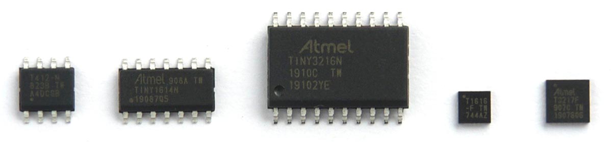
A few years back, Microchip/Atmel announced the release of a completely new range of chips designed to serve as replacements for their older ATmega and ATtiny ranges. The new ATtiny chips started with the 1-series which included ATtiny417 and ATtiny817, which was followed in 2018 by the cheaper 0-series microcontrollers which included microcontrollers like the ATtiny1604 and ATtiny402. The new range of microcontrollers now comprises of a total of 25 parts. However, for makers, DIY Hobbyists and fans of the Arduino development platform, it was not a celebration as there was no support to enable programming of the mcus using the Arduino IDE. This however changed some months ago when the megaTinyCore was released as an Arduino core to support programming of the new range of Atmel microcontrollers. For today’s tutorial, we will look at the process of using the megaTinyCore to program one of these new ATtiny microcontrollers using the Arduino IDE.
The MegaTinyCore is an Arduino core for programming the new series of Microchip microcontrollers with the Arduino IDE. The Core is based on the work done by the Arduino team during the development of support for their new ATmega4809-based boards. While the core provided everything we needed to compile code for the new microchip series boards, there was still a slight problem as the ATtiny 0- and 1-series can only be programmed through a Unified Program and Debug Interface (UPDI) (a 1-wire interface using the reset pin on the ATtiny) because they do not have a bootloader, and as such cannot be programmed via ISP or with ISP programmers. To solve this problem, GitHub user ElTangas wrote a UPDI programmer which can be uploaded to an Arduino Uno or equivalent board to turn the board into a UPDI programmer for the new series board, giving users the ability to not only develop their code with the Arduino IDE, but also upload the code to their target microcontroller using the Arduino board as the programmer, totally eliminating the need for Atmel studio in the development process.
Based on the above, this tutorial will show how you how to set up an Arduino board as the UPDI Programmer and the process of setting up the megaTinyCore on your Arduino IDE.
Required Components
The following components will be needed to follow this tutorial:
- Attiny412
- An Arduino Uno or nano
- Adafruit 8-pin SOIC
- 4.7k Resistor
- 1ouf Capacitor
- Breadboard
- Jumper Wires
None of the new ATtiny devices are available in DIP packages, as such, to connect them on a breadboard, you will need a sort of breakout board which is why the Adafruit 8-pin SOIC is being used for. For microcontrollers with more pins, you can check out their 14 and 20 pin SOIC or these 24-pin VQFN board on Amazon. All of these components can be bought from the majority of online electronics component stores.
With all the components in place, we can start by Installing the megaTinyCore on the Arduino IDE.
Installing the MegaTinyCore
The megaTinyCore requires Arduino IDE version 1.6.3 or later although it was stated on its GitHub page that it may require a much more recent version of the IDE but the initial test was done with version 1.8.9.
The megaTinyCore can be installed on the Arduino IDE in two ways;
- Installation via the Arduino Board Manager
- Manual Installation
I will explore both methods and let you decide which is easiest or faster.
1. Installation via the Arduino Board Manager
The Arduino board manager was designed to make the installation of new boards and add-ons easy for users. To install the megaTinyCore using this method, follow the steps enumerated below;
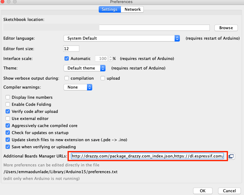
- Open the preferences window from the Arduino IDE. Go to File > Preferences or Arduino > Preferences if working from a macOS
- On the preferences window, locate the “Additional Board Manager URLs” text box and enter http://drazzy.com/package_drazzy.com_index.json into the field as shown below and click the OK button
Add the Link to Additional Board URL List - Next, open the Arduino board manager. Go to tools>Boards>Boards manager
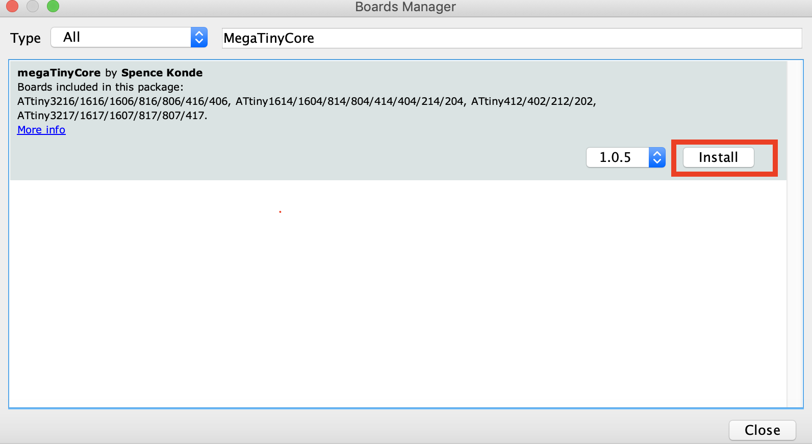
- When the board manager opens up, enter megaTinyCore into the search bar and scroll, you will see “megaTinyCore by Spence Konde”, click on install as shown below.
- Also, search for the “Official Arduino megaAVR boards” package and install the most recent version of that too.
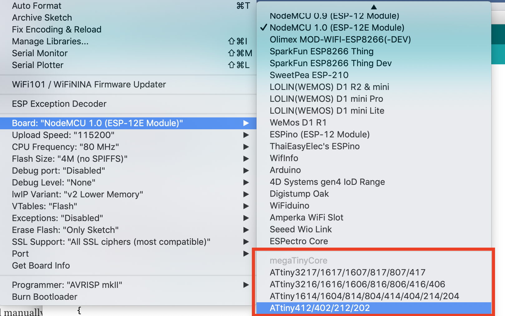
With all of that done successfully, you should now see the Attiny boards all listed under the boards’ section (tools -> Boards) of the Arduino IDE. If that is so, it means the board installation was successful.
2. Manual Installation
The Arduino board manager method provides some level of automation while the manual installation, on the other hand, allows the latest version of the core to be installed, with fixes that may not yet be available in the board manager version of the core. However, to use the manual installation, it is required that you use board manager to install the latest version of the Official Arduino megaAVR board package for manual installation to work.
Manual installation is recommended if you are interested in contributing to the development of the core, or if having the latest fixes which are not in the released version is important to your build.
To install manually, follow the steps below;
- Ensure you have installed the latest version of the Official Arduino megaAVR board package.
- Download the MegaTinyCore.zip package (either the “released” version or by downloading the .zip of the master repo) on your computer.
- Extract, and place the file in the “hardware” folder inside your sketchbook folder (where your Arduino Sketches are saved). If the hardware folder does not exist, create a new folder and name it “hardware”.
- Restart the Arduino IDE
For automatic updates, instead of downloading the zip file, you can download the GitHub client, and sync this repo to the hardware subfolder of your sketchbook folder.
With the installation steps completed, you should now see the Attiny boards all listed under the boards’ section (tools -> Boards) of the Arduino IDE if the installation process was successful.
With that done, the next step is to set up a UPDI programmer after which you will be ready to upload code to any of the new attiny series Microchip microcontrollers.
Make the UPDI Programmer
As mentioned during the introduction we will need to make a UPDI programmer to be able to upload code to the attiny series using the IDE and an Arduino board.
There are two steps to doing this. The first step involves transforming an Arduino board to serve as the UPDI programmer while the second part shows how to connect the Attiny to the programmer and the Upload process.
1. Transform an Arduino to a UPDI programmer
To transform our Arduino board to a UPDI programmer, we will use the UPDI Arduino sketch created by ElTangas. The sketch converts ATmega328(p)-based Arduino’s, like the Arduino UNO, Nano, and Pro mini, into a UPDI programmer. The sketch, however, does not work on boards based on other microcontrollers, like the 32u4 (on Arduino Micro/Leo) or any non-AVR board.
The following steps show how to make this cheap UPDI programmer;
- Close all instances of the Arduino IDE to avoid errors.
- Download and extract the UPDI programmer sketch
- Open the jtag2updi folder after extracting the download
- Open the sketch jtag2updi.ino and upload it to the Arduino board you will like to use which for our sake is an Arduino Nano. When you open the code, the .ino file will appear empty and that is fine as all the code is contained in the other files in the same folder as the .ino, but the empty .ino is needed so they can be compiled by the IDE.
With upload successful, you are now ready to use the UPDI programmer. If you use the new ATtiny series a lot, it will be a smart move to totally dedicate an Arduino pro mini or nano board as a permanent UPDI programmer.
2. Connecting the Attiny and uploading
Connect the ATiny to the Arduino as shown in the schematics below;
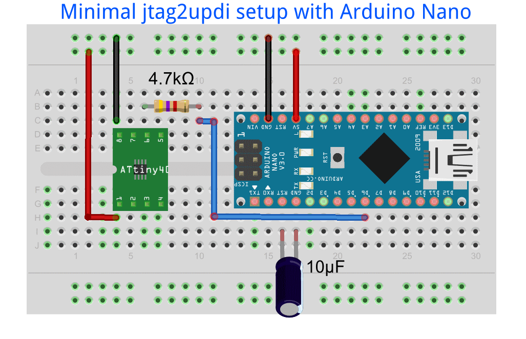
The connection is quite straightforward but pin-pin connection between the Arduino and the Attiny is illustrated below to prevent mistakes;
Arduino Nano – Attiny
GND - GND
5V - VCC
D6 - UPDI
With the microcontroller connected to your Arduino UPDI programmer, we are now ready to upload code to the attiny.
Open or write the code you would like to upload. Verify the code to ensure that there is no error, then go to Tools -> Board, and scroll down till you see the ATtiny you are working with on the list and select it.
This should update the parameters being displayed when you click tools. Now we need to tell the Arduino IDE to use our programmer. To do this, go to Tools->Programmers (towards the end).
Scroll down on the pane and select jtag2updi (megaTinycore) as your programmer.
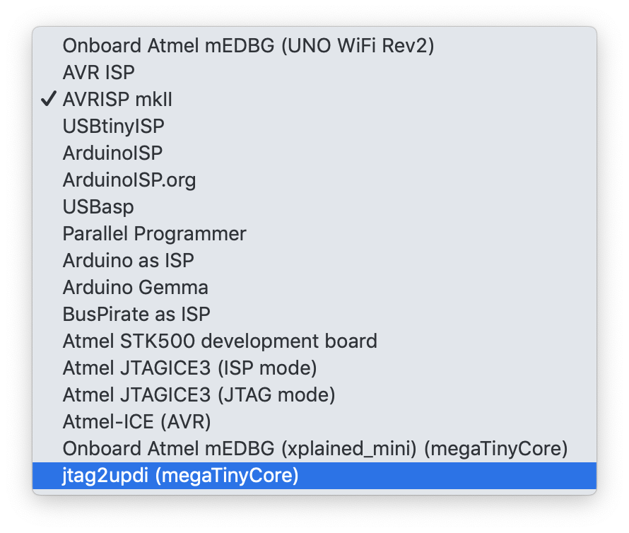
With that done, your screen should now look like the image below when you click on tools;
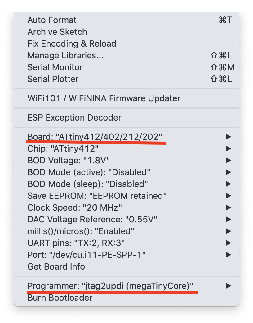
This means all lights are green. Now select the port to which the Arduino nano is connected and hit the upload button on the IDE. You should immediately see the upload process and when complete, the microcontroller should perform as programmed.
Compared to the former ATtiny microcontrollers, these new series of MCUs come with higher amount of flash memories, cost a whole lot less and are all-round more efficient compared to the previous set as such they should probably be considered when next you are making the choice of a tiny low-cost, low-power microcontroller for your project.
References:


The UPDI Programmer Sketch (https://github.com/SpenceKonde/jtag2updi, jtag2updi.ino) is empty…
Sorry, not sure i get your question/comment
Hi there,
Thanks for the good article. Is it possible to upload a HEX file already compiled by ATMEL STUDIO by this method. If yes how to ?
regards
Sajeev
Dear friend, perfect tutorial very helpful.
I programmed an Attiny406 microcontroller successfully, however, I have a problem with pwm outputs.
For example I am uploading the following code which it is working perfect on Nano but not on the microcontroller Attiny406. Same issue on MH-Tiny board.
On Attiny406 I am using pin2 (0 on code) for input and pin7 (5 on code) for output
http://ww1.microchip.com/downloads/en/DeviceDoc/Microchip%208bit%20mcu%20AVR%20ATtiny406%20data%20sheet%2040001976A.pdf
sensorValue = analogRead(pot);
// map it to the range of the analog out:
outputValue = map(sensorValue, 0, 1023, 10, 250);
analogWrite(led, outputValue);
any suggestions?
Regards
Try declaring the variables as float,
Using above parts and procedure can i do programming of tiny202/402
avrdude: jtagmkII_initialize(): Cannot locate “flash” and “boot” memories in description
how to solve this