

Using the Geekcreit ILI9325 2.8″ Touchscreen display with Arduino
- Nick Koumaris
- http://educ8s.tv
- info@educ8s.tv
- 9.204 Views
- moderate
- Tested
- 0 Likes

We’ve done quite a number of tutorials on the use of several displays with Arduino boards and today we will add another tutorial to that list. We will look at the ILI9325 based 2.8″ touchscreen display shown below and how it can be used with the Arduino to deliver a better user experience for your projects.

For today’s tutorial, we will use the ILI9325 driver based, 2.8″ display from Geekcreit. The display comes as a shield so it’s ready to be used for Arduino based projects. It is an 18-bit color display with a total of 262,000 different color shades. The display has a resolution of 240 x 320 pixels with individual pixel control.
Today’s project involves some very simple tasks which we will use to demonstrate the capabilities of the display. We will create a button which when touched, will trigger the Arduino to display a message on the screen. At the end of today’s tutorial, we would have gone through how to create a user interface on the touchscreen, how to detect when the screen is touched and how to display data on the screen.
Required Components
The following components/parts are required to build this project:
The Arduino Mega or any of the other Arduino board can be used for this project and the power bank comes in handy when the project is to be used in a standalone mode. As usual, the exact components used for this tutorial can be purchased via the links attached to each of them.
Schematics
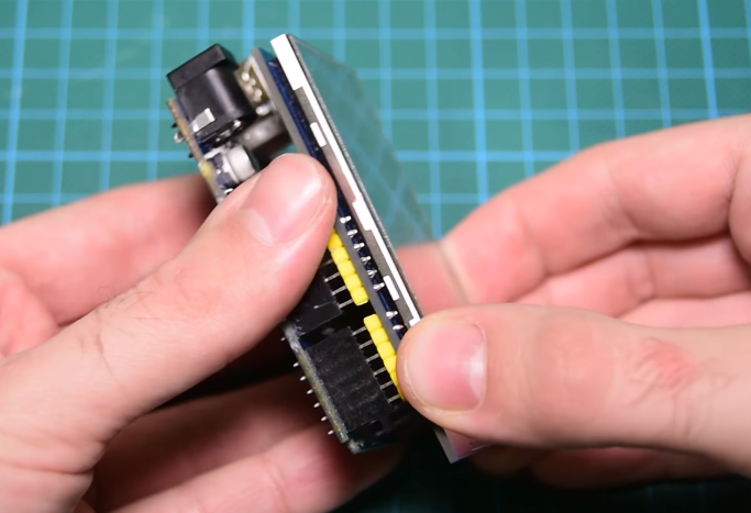
The 2.8″ TFT display used for this project comes as a shield with the form factor of the Arduino Uno. This makes it easy to connect the shield to boards like the Uno, Mega and Due, as all we need to do, is plug it directly into the board, eliminating all the mess made by wires. Plug the display to the Arduino as shown in the image below.
The fact that the display comes as a shield becomes a disadvantage when its used with the Arduino Uno as it occupies almost all the pins leaving just 2 digital pins and one analog pin for other uses. This can however, be overcome by using either the Arduino Mega or Due as they both work perfectly well with the display.
Code
The code for this tutorial is heavily reliant on a modified version of Adafruit’s TFT LCD, GFX and touchscreen libraries. These libraries can be downloaded from the links attached to them.
As mentioned earlier, our focus for this tutorial will be to demonstrate, how UI can be created on the display and interpret touches to trigger actions. To achieve this, we will develop a simple sketch which displays a Youtube subscribe button. When the subscribe button is pressed, a text is displayed on the screen.
To do a quick run through the code, we will start by including the libraries that will be used for the project.
//Written by Nick Koumaris
// info@educ8s.tv

#include <Adafruit_TFTLCD.h>
#include <Adafruit_GFX.h>
#include <TouchScreen.h>
Next, we declare the pins of the Arduino to which the display is connected.
#define LCD_CS A3
#define LCD_CD A2
#define LCD_WR A1
#define LCD_RD A0
#define LCD_RESET A4
Calibration needs to be done before the touchscreen functionality of this display can be used. To calibrate the screen, we upload the code and Open the Serial Monitor to obtain the values of the display’s edges. Click (touch) on the top left corner of the display and write down the X and Y values displayed on the serial monitor. Then we edit the code to reflect those values. The X value goes to the TS_MAXX variable and the Y value goes to the TS_MAXY variable. Next, click on the bottom right corner of the display and enter the values displayed on the serial monitor for the TS_MINX and TS_MINY variables. With this done our display is now calibrated and ready for use.
#define TS_MINX 204
#define TS_MINY 195
#define TS_MAXX 948
#define TS_MAXY 910
Next, we declare the colors to be used with their hexadecimal values and we create an object of the Adafruit TFTLCD library, indicating the variables used to represent the pins of the Arduino to which the display is connected.
#define BLACK   0x0000
#define BLUE    0x001F
#define RED     0xF800
#define GREEN   0x07E0
#define CYAN    0x07FF
#define MAGENTA 0xF81F
#define YELLOW  0xFFE0
#define WHITE   0xFFFF
Adafruit_TFTLCD tft(LCD_CS, LCD_CD, LCD_WR, LCD_RD, LCD_RESET);
We also create an object of the touchscreen library indicating, the pins of the Arduino to which, the touch part of the screen is connected.
TouchScreen ts = TouchScreen(XP, YP, XM, YM, 300);
next, we write the Setup function.
We start by initializing the serial monitor and the display. After this, we set the orientation of the LCD and fill the screen with a black color to serve as the background.
void setup() {
  Serial.begin(9600);
  Serial.print("Starting...");

  tft.reset();
  tft.begin(0x9325);
  tft.setRotation(1);

  tft.fillScreen(BLACK);
next, we draw a white frame on the display, set the text cursor to the desired location, change its color to white, and print the “Hello” text on the screen. By following the same procedure, we display the red YouTube text as well.
//Draw white frame
  tft.drawRect(0,0,319,240,WHITE);

  //Print "Hello" Text
  tft.setCursor(100,30);
  tft.setTextColor(WHITE);
  tft.setTextSize(4);
  tft.print("Hello");

  //Print "YouTube!" text
  tft.setCursor(80,100);
  tft.setTextColor(RED);
  tft.setTextSize(4);
  tft.print("YouTube!");
Next, we create the red Youtube subscribe button. To achieve this, we create a red rectangle and for our size requirements, we set the x and y pixel coordinates of the top left corner point of this rectangle to (60,180), define its width as 200 pixels, its height as 40 pixels and set pixel coordinates for the bottom right of the rectangle to (260, 220). To make the rectangle look more like a button, we draw a similar white rectangle outside of the red rectangle and write the “Subscribe” text on it.
//Create Red Button
  tft.fillRect(60,180, 200, 40, RED);
  tft.drawRect(60,180,200,40,WHITE);
  tft.setCursor(80,188);
  tft.setTextColor(WHITE);
  tft.setTextSize(3);
  tft.print("Subscribe!");
With the setup function all done, we move to the loop function, the algorithm in operation for the loop section is simple, each time the user clicks on the screen, we convert the point coordinates of the touch point into pixels using the Map function. After conversion, if that point is inside the red rectangle area, it means that the user has pressed the button, so we disable the button by setting this variable to false and we clear the screen so to display the “Thank you for Subscribing” message on the screen.
void loop()
{
  TSPoint p = ts.getPoint();  //Get touch point

  if (p.z > ts.pressureThreshhold) {

   Serial.print("X = "); Serial.print(p.x);
   Serial.print("\tY = "); Serial.print(p.y);
   Serial.print("\n");

   p.x = map(p.x, TS_MAXX, TS_MINX, 0, 320);
   p.y = map(p.y, TS_MAXY, TS_MINY, 0, 240);

   if(p.x>60 && p.x<260 && p.y>180 && p.y<220 && buttonEnabled)
   // The user has pressed inside the red rectangle
   {
    buttonEnabled = false; //Disable button

    //This is important, because the libraries are sharing pins
   pinMode(XM, OUTPUT);
   pinMode(YP, OUTPUT);

    //Erase the screen
    tft.fillScreen(BLACK);

    //Draw frame
    tft.drawRect(0,0,319,240,WHITE);

    tft.setCursor(50,50);
    tft.setTextColor(WHITE);
    tft.setTextSize(3);
    tft.print("Thank you for\n\n   subscribing!");
   }
   delay(10);
  }
}
The complete code for this project is below and also attached under the download section.
   //////////////////////////////////////////////
  //        2.8" TOUCH SCREEN DEMO            //
 //                                          //
//           http://www.educ8s.tv           //
/////////////////////////////////////////////

#include <Adafruit_TFTLCD.h>
#include <Adafruit_GFX.h>
#include <TouchScreen.h>

#define LCD_CS A3
#define LCD_CD A2
#define LCD_WR A1
#define LCD_RD A0
#define LCD_RESET A4

#define TS_MINX 204
#define TS_MINY 195
#define TS_MAXX 948
#define TS_MAXY 910

#define YP A2  // must be an analog pin, use "An" notation!
#define XM A3  // must be an analog pin, use "An" notation!
#define YM 8   // can be a digital pin
#define XP 9   // can be a digital pin

#define BLACK   0x0000
#define BLUE    0x001F
#define RED     0xF800
#define GREEN   0x07E0
#define CYAN    0x07FF
#define MAGENTA 0xF81F
#define YELLOW  0xFFE0
#define WHITE   0xFFFF

Adafruit_TFTLCD tft(LCD_CS, LCD_CD, LCD_WR, LCD_RD, LCD_RESET);
TouchScreen ts = TouchScreen(XP, YP, XM, YM, 300);

boolean buttonEnabled = true;

void setup() {
  Serial.begin(9600);
  Serial.print("Starting...");

  tft.reset();
  tft.begin(0x9325);
  tft.setRotation(1);

  tft.fillScreen(BLACK);

  //Draw white frame
  tft.drawRect(0,0,319,240,WHITE);

  //Print "Hello" Text
  tft.setCursor(100,30);
  tft.setTextColor(WHITE);
  tft.setTextSize(4);
  tft.print("Hello");

  //Print "YouTube!" text
  tft.setCursor(80,100);
  tft.setTextColor(RED);
  tft.setTextSize(4);
  tft.print("YouTube!");

  //Create Red Button
  tft.fillRect(60,180, 200, 40, RED);
  tft.drawRect(60,180,200,40,WHITE);
  tft.setCursor(80,188);
  tft.setTextColor(WHITE);
  tft.setTextSize(3);
  tft.print("Subscribe!");

}

void loop()
{
  TSPoint p = ts.getPoint();  //Get touch point

  if (p.z > ts.pressureThreshhold) {

   Serial.print("X = "); Serial.print(p.x);
   Serial.print("\tY = "); Serial.print(p.y);
   Serial.print("\n");

   p.x = map(p.x, TS_MAXX, TS_MINX, 0, 320);
   p.y = map(p.y, TS_MAXY, TS_MINY, 0, 240);

   if(p.x>60 && p.x<260 && p.y>180 && p.y<220 && buttonEnabled)// The user has pressed inside the red rectangle
   {
    buttonEnabled = false; //Disable button

    //This is important, because the libraries are sharing pins
   pinMode(XM, OUTPUT);
   pinMode(YP, OUTPUT);

    //Erase the screen
    tft.fillScreen(BLACK);

    //Draw frame
    tft.drawRect(0,0,319,240,WHITE);

    tft.setCursor(50,50);
    tft.setTextColor(WHITE);
    tft.setTextSize(3);
    tft.print("Thank you for\n\n   subscribing!");
   }
   delay(10);
  }
}
Demo
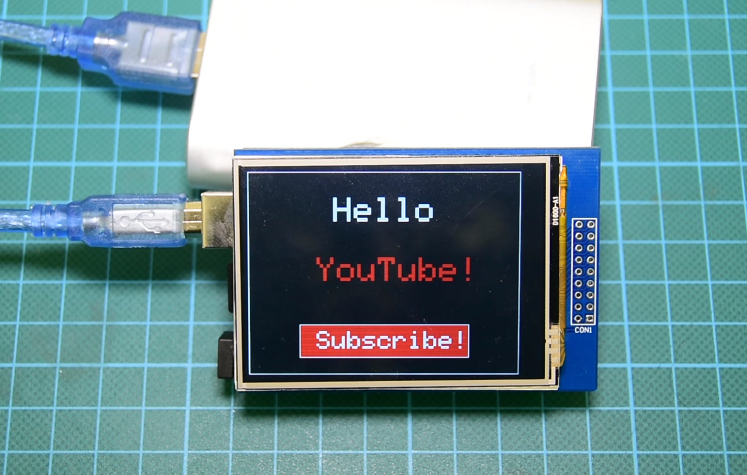
Copy the code above and create a new Arduino sketct. Ensure the libraries are installed and upload the code to the setup described under the schematics section. Once the upload is complete, you should see the display come up as shown below.
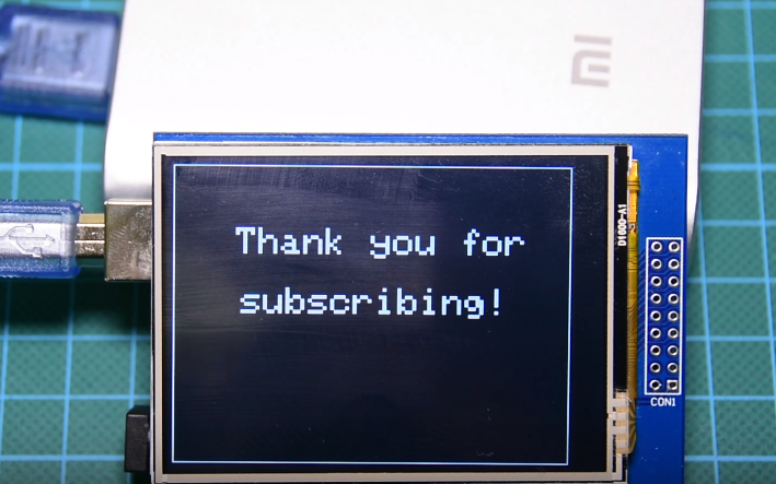
As soon as the subscribe button is pressed, the screen below is displayed.
That’s it for this tutorial guys. Feel free to expand this code for use in your projects and do not hesitate to let me know via the comment section if you have any questions.
Till Next time.
The video version of this tutorial is on youtube.


