

Tape Head Pre-Amplifier
- Rajkumar Sharma
- 32.401 Views
- medium
- Tested
- SKU: EL34135
- Quote Now
- 0 Likes

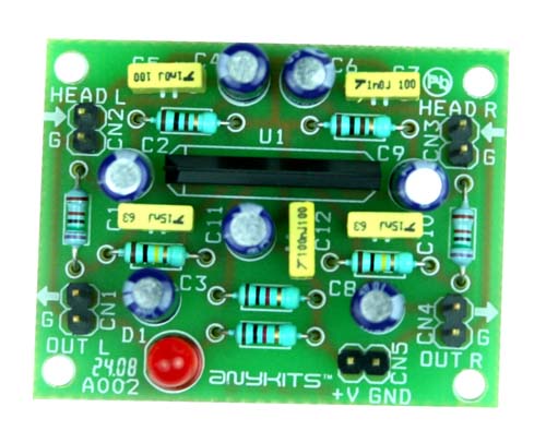
This project is a tape head Pre-Amplifier circuit.
Description
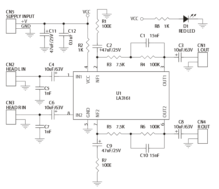
The circuit is built around a popular Sanyo stereo head preamp IC LA3161. Low electrical signals from the playback heads are fed to pins 1 and 8 of IC1 via DC decoupling capacitors, respectively. Components between pins 2 and 3 and pins 6 and 7 provide adequate equalization to the signals for normal tape playback.
Specifications:
- Power supply: 9 ~ 12 VDC @ 20 mA
- Output power: up to 200 mW
- Input Resistance – 100 KΩ (Typ), Load Resistance – 10 KΩ (Typ)
- Low noise, good ripple rejection owing to the on-chip voltage regulator
- Berg pins for connecting power supply, input and output
- Power-On LED indicator
- Four mounting holes of 3.2 mm each
- PCB dimensions 49 mm x 38 mm
Schematic
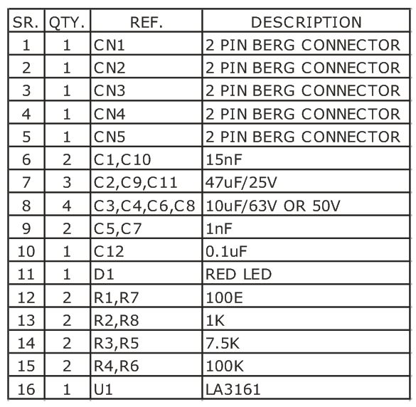
Parts List
LA3161 Datasheet
Please follow and like us:
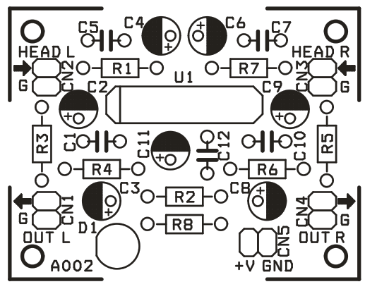
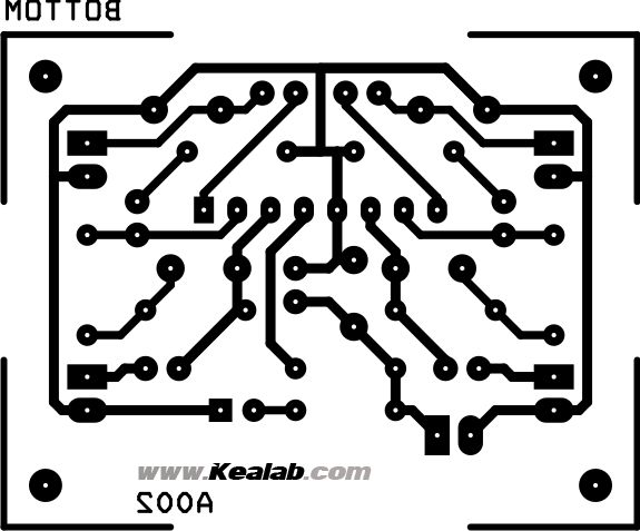
PCB


sir ! i want to make a lapel-like project. could you recommend something ?
good day, is there any circuit for tape head for erasing tape?
We are sorry, we don’t have such circuit for erasing tape.
I want to buy this pre amp circuit. How can I buy?
We can manufacture this for you if order is >15 pieces
How much for 15pcs? And how long would they take?
Kindly send the price for 15pcs. I need.
check your email, please.
In the project for the stereo tape head preamp I can’t find the PCB diagram!
I’ve uploaded PCB in PDF format in downloads above. Thanks
Sir can i use circuit for as pjonopreamp
What do you mean with “pjonopreamp” ?
Hi, what amp will be good for this preamp? I’m trying with the lm386 but I have to put two of them in serie to hear something, and with a little perturbation the sound starts to go crazy. I’m very newbie on this. thanks
Any power amp will do the job. You can try this one: https://www.electronics-lab.com/project/6-5w-stereo-audio-amplifier/
How much would they cost if I ordered 15+ pieces? And how long would they take to build?
check your email, please.
Could we revisit this again? I never got your last email, I don’t believe…..Could you send it again?
Do you have the same kind of tape head pre amplifier but in a smaller size? It’s for a Walkman prototype
Sorry, no, but you could design it with SMD components to make it smaller.
Can we connect the tape head, a 3.5 mm jack and use it on a 3,7 V battery?
You can use a 3.5 Jack but it will not work with 3.7V battery, it needs at least 9V
Do you have an another Tape Head Pre-Amplifier can work on 3V Batteries and a 3.5 mm jack output too?
Sincerely
Meaxy
Sorry, no
Could I get a quote for order of 15?
Please check your email for a quote.
What equalization is this amp for? Meaning speed — 7.5, 3.75 ips? Can it be modified for cassette playback?
Yes this is ideal for cassette playback and you can adjust the equalization per need, please refer to the datasheet above.
Could I get a quote for 30pcs please?
check your email, please.
I have a very old british built domestic reel to reel tape deck that uses valves for internal circuits. The electronics are not working but I only need it for playback. The tape speed is 3.75IPS. Is this circuit suitable. Does it have the correct eq curve. Can it work from a 9v battery and if so how many hours