

LED Binary Clock – Arduino Shield Compatible
- Alexandru Stan
- http://hypertriangle.com/~alex
- alex@hypertriangle.com
- 9.216 Views
- medium
- Non tested
- 0 Likes

This shield is meant to be used as a Binary Clock on top of an Olimexino-5510. Other ‘duinos might work too.
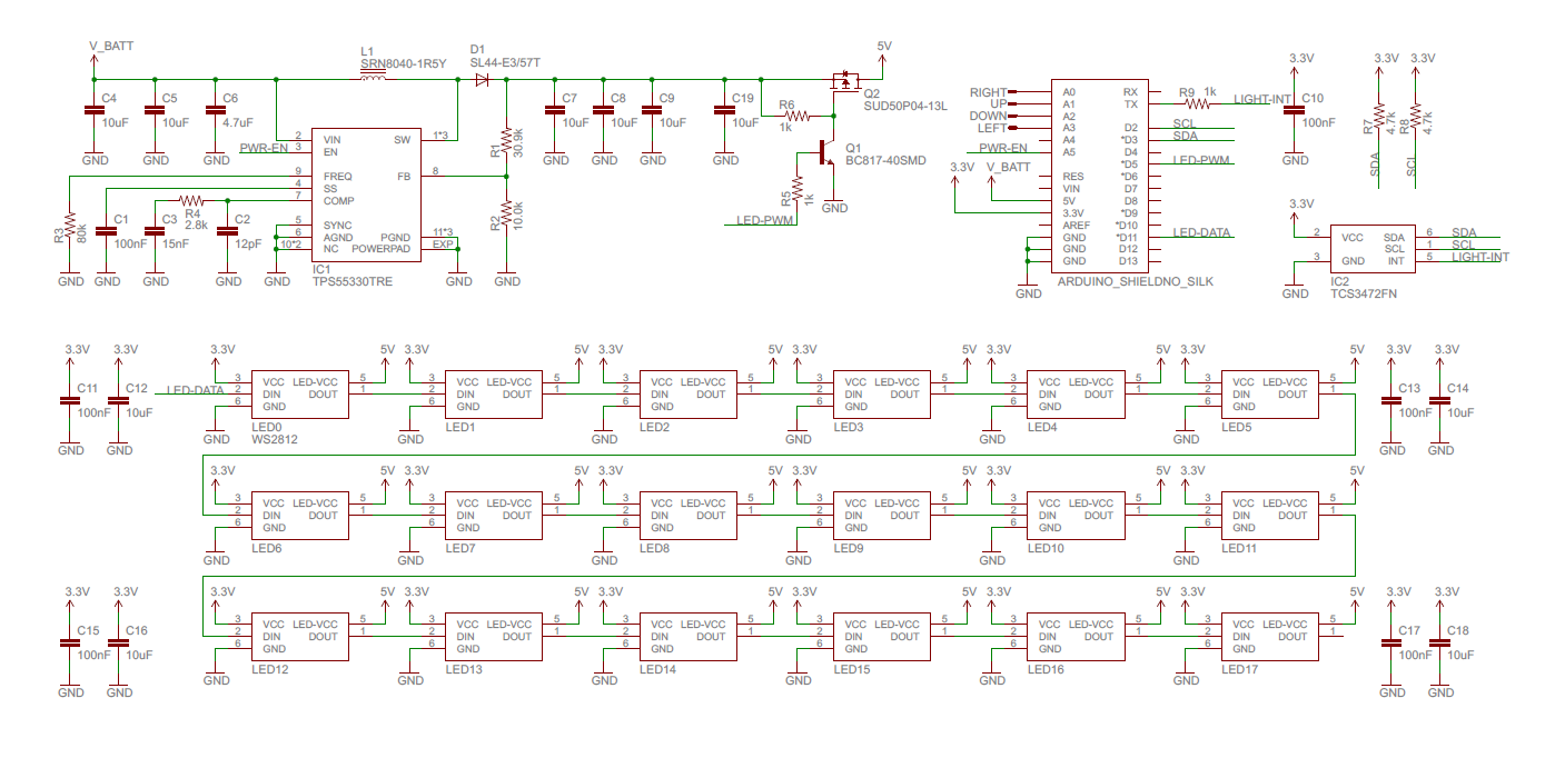
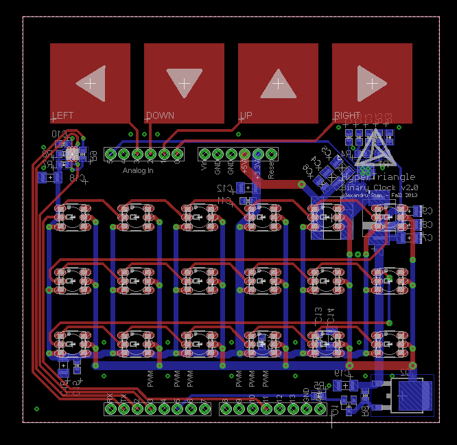
Schematic
Description
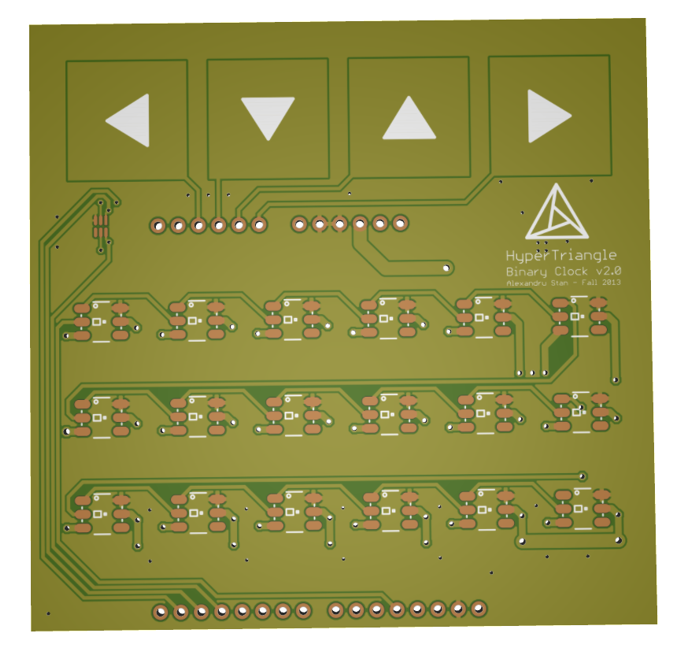
LED Matrix
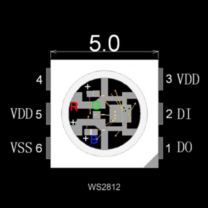
The main feature of the Clock is the 6×3 WS2812 RGB led matrix. These leds contain a little controller that accept a serial protocol for the color data and they handle the PWM. They’re also chainable meaning that only one pin(D11, LED-DATA) is required to quite all of them. The protocol is described in the WS2812 datasheet, there exist a couple of libraries that handle them, including one for Arduino. In my case i’m using an ASM library for the MSP430.
Power Supply
The Olimexino-5510 has a connector for a battery. But it just connects the battery to the 5V rail, the battery could go as low as 3V. The WS2812 aren’t meant to run that low, specifically the Blue led get a lot dimmer. In order to fix this I incorporated a SMPSU that can get 5V from the battery voltage. It could in theory handle as much as 2A. The design was done with TI Webench, all parts are the same as the suggested ones.
The WS2812 leds are very bright, so in the darkness this might be a problem. One could dim them by sending them a darker color but this reduces resolution. Q2’s purpose is to PWM is the 5V that the LEDs in order to dim them externally. This essentially gives another scaling factor for the brightness. It’s a similar principle to how dynamic contrast works in TVs.
Capacitive Touch Pads
This shield contains 4 touch pads for UI purposes. The MSP430 chips have a nice peripheral where one can make an RC oscillator out of any pin, by measuring the frequency of this oscillator one can determine the capacitance of the touch pad. TI offers a library for capacitive touch: http://www.ti.com/tool/capsenselibrary
Light Sensor
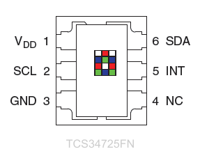
The shield also has a light sensor, meant to measure ambient brightness. One can use this to make the display’s brightness match the room. The sensor is connected via I2C, since neither the Arduino nor the Olimexino-5510 have I2C exposed on the pins I will have to do a software solution for this. The TCS34725FN sensor is also capable of measuring RGB color; I’m sure something fun can be accomplished using that.
Olimexino-5510
The olimexino-5510 chip contains an MSP430F5510. The board has USB capabilities(I’ll make use in that in order to sync the clock with the computer).
Parts
| D1 | |
| L1 | |
| U1-power | |
| U2-sensor | |
| Q1-pmosfet | |
| Q2-npn | |
| 2x Male Header Pins(40 pos) | |
| C1, C10, C11, C13, C15, C17 | 6x 100nF |
| C4, C5, C7, C8, C9, C12, C14, C16, C18 | 9x 10uF |
| C2 | 12pF |
| C3 | 15nF |
| C6 | 4.7uF |
| R1 | 30.9k 1% |
| R2 | 10.0k 1% |
| R3 | 82.5k |
| R4 | 2.8k |
| R5,R6 | 2x 1k |
| R7,R8 | 2x 4.7k |
| Charging Resistor for olimexino | 2k |
| 18x WS2812 | |
| Olimexino-5510 | |
| 6600mAh battery |
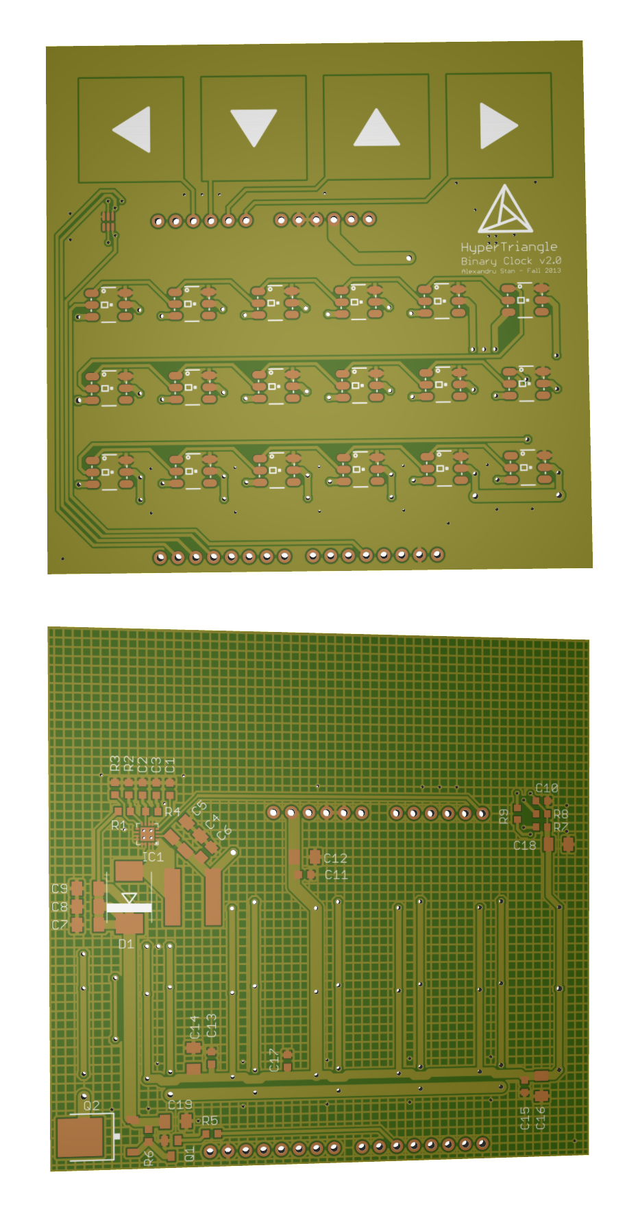
PCB


 – Open-Source Arduino Nano Hardware")