

Automatic School Bell
- Jahanzeb Gul
- jahanzebgul89@gmail.com
- 46.954 Views
- medium
- Non tested
- 0 Likes

Description
This project is an Automatic School bell system. Such a system triggers a bell (or operates any other load) at predifined time. In this version some advanced features are introduced:
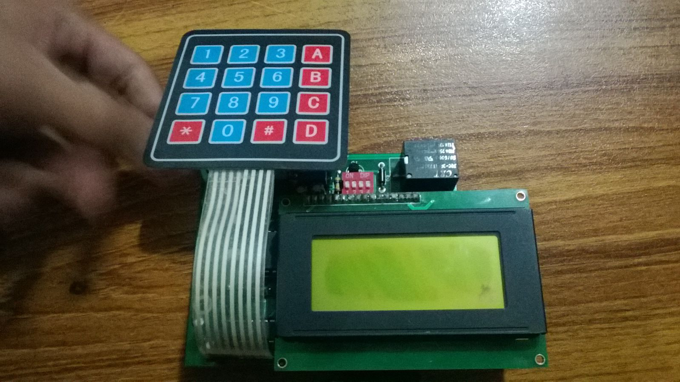
- 16×2 LCD Display ( Displays current date, time and day)
- 4×4 Keypad for Inputs
- Stand alone product ( no PC required to program or maintain ringing schedule)
- No battery required to maintain clock and ringing schedule
- Variable ringing time
- Max 10 bells can be set
- Custom Weekend filters
- Monthly OFF / Weekly OFF
- Half Day
- Total AC Power Handling : 1000W (240V 5A)
- Connect as many AC electronic bells in parallel form
- Built-in back up battery supply
- Built in permanent memory for bell timings
- Auto-memory scan on system startup
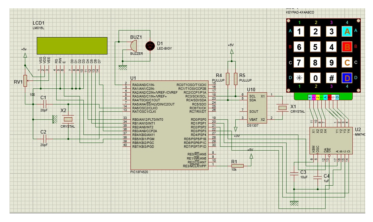
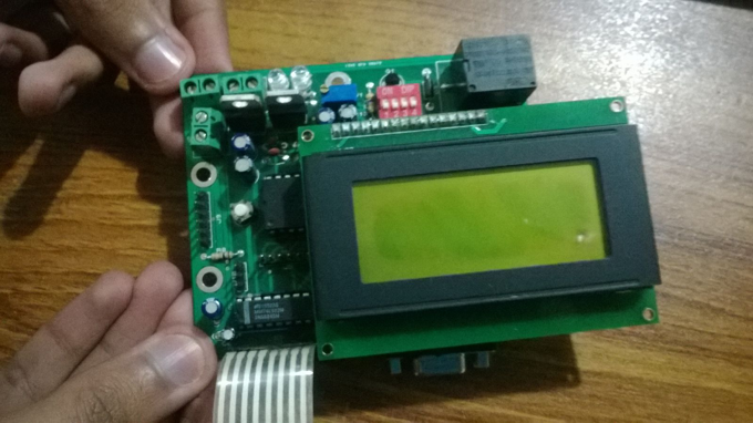
I used PIC18f4520 microcontroller as the brain of the system. RTC1307 IC is used to maintain the clock,date and day with a 3V backup voltage battery. Bell timings are stored in the internal EEPROM of mcu.
MCU is reading time from RTC through I2C Serial protocol and compares the current time with stored memory time in a continous while(1) loop.
MM74C922 decoder IC is used for keyboard. Reading the sixteen buttons is done using 4-bits output of decoder IC.
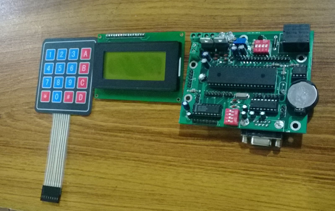
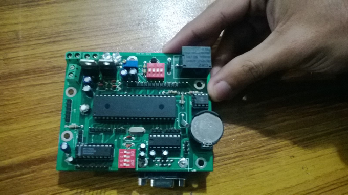
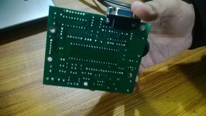
Photos
Please follow and like us:
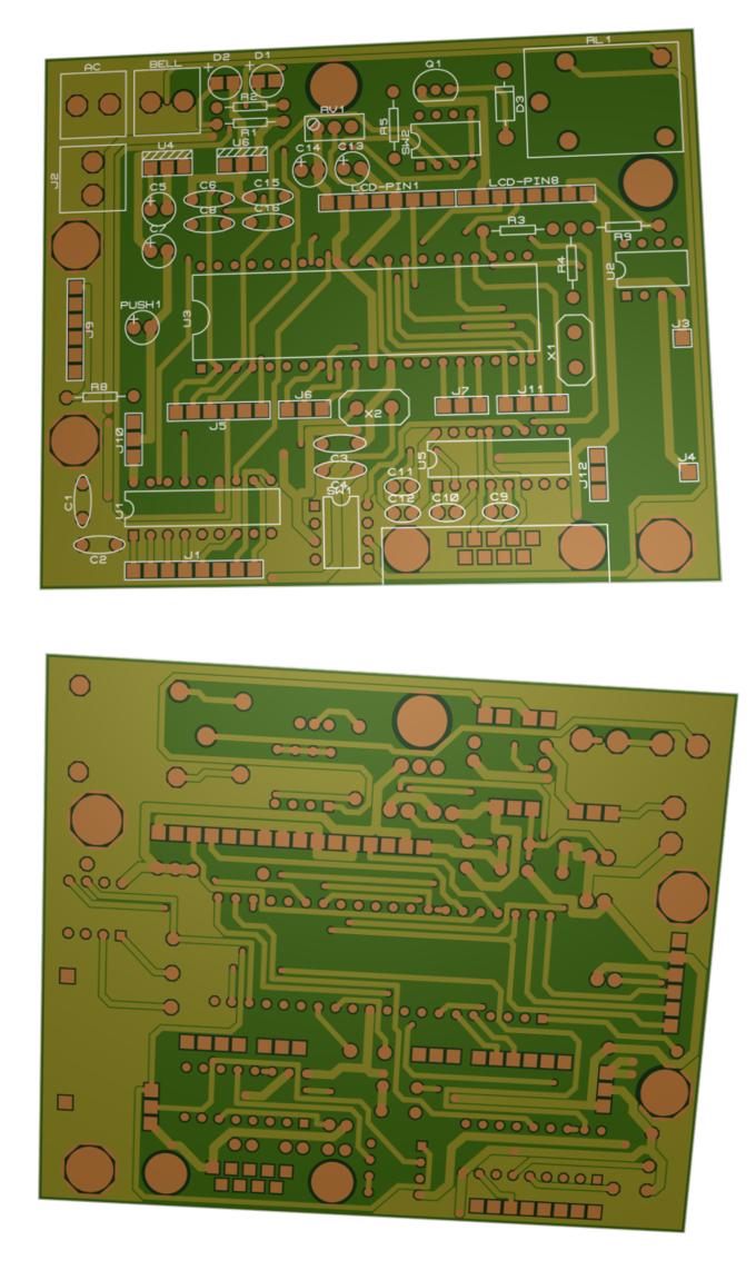
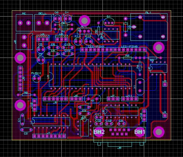
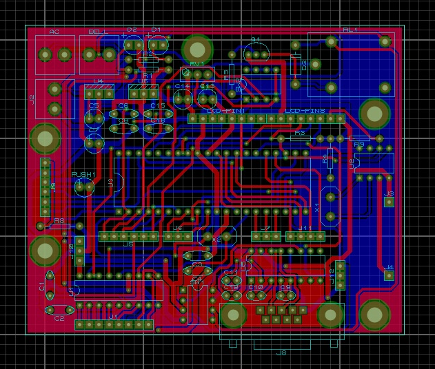
PCB


I need a code for automatic college bell without an LCD display,,, for a group project
Iam student. Iwant to present this project in final year. Could you please send me program to my mail
amarnadhvelpula2468@gmail.com
sir i want this code of bell so plz send my e mail 17139006@gift.edu.pk quickly sir
I request to be sent this project to present it in a school project