

Toggle ON / OFF Switch with a single push-button
- Michail Papadimitriou
- 212.575 Views
- easy
- Tested
- SKU: EL36918
- Quote Now
- 1 Likes

This project describes how to build a “soft touch” switch. By “soft touch” we mean that you have to push once to set the device ON and push again to set the device OFF. This kind of switch works by latching a relay to ON state with the push of a button and with another push latch is released. It is working like flip-flop states. In that way, you can control power to a device using one push button.
The circuit is built around a 555 timer configured in a way that let it latch on one state and action is required to change state. The circuit is powered from +5V and there are connectors to connect the controlling device. Inspiration from this project and circuit is found here: http://todbot.com/blog . We added a relay on output, an indicator led as well as connectors for power, external push button, and relay contacts.
Schematic
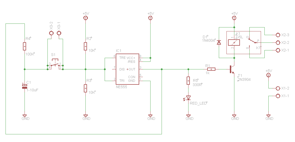
The Schematic for this circuit can be seen above. The circuit toggles a relay when button S1 is pressed. The operation of this circuit is simple. Pins 6 and 2 of 555 timer are at half power voltage. When output pin 3 is high then capacitor C1 is charged and when it’s low capacitor is discharged. When the button is pressed capacitor voltage appears on pin 6 and 2 and output pin 3 changes state as well as capacitor voltage changes. So when output is high capacitor has +5V. When we press the button pin 3 goes low and the capacitor goes 0V, when we press the button again output goes high again, so we have toggle functionality. When the output is high transistor T1 is conducting current and the relay is latched when low relay is released. Diode D1 is used to protect the transistor from back voltage generated when the relay goes off.
A disadvantage of this circuit is that when we connect power to the circuit relay is engaged. A solution to this can be found on the second reference website below.
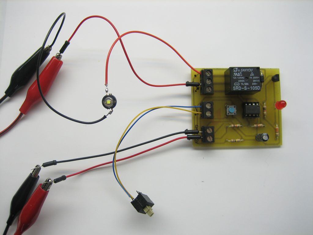
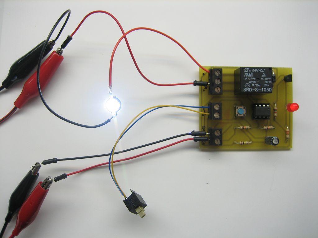
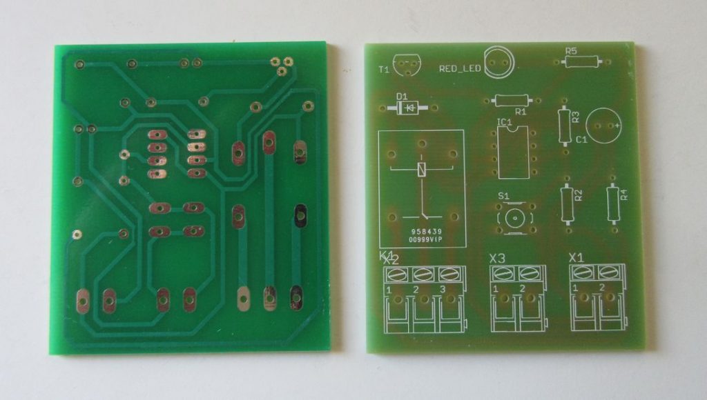
Photos
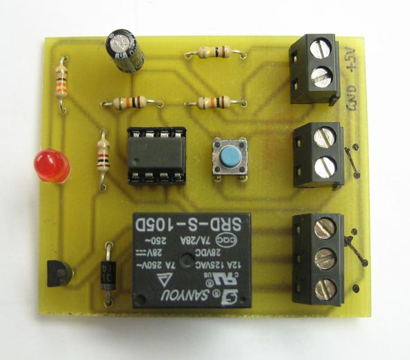
PCB
References
- http://todbot.com/blog/2010/01/02/momentary-button-as-onoff-toggle-using-555/
- http://www.bowdenshobbycircuits.info/page9.htm#555-T.gif
PCB
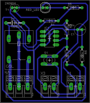


tested works as explained
we have require pcb circuit on off with one push button
Thank you very much
Gracias, Nice work. I guess it uses Mono stable multi vibrator. Cheers
I need two relays output with a momentary output (1 second or less) instead of constant output, each (swaping, one relay momentarily on, the other off, vice versa) . This is to replace mechanical switch of car power door lock with one push-on button. Can you modify the circuit? Thanks.
It is rare to see schematic with 555 for this purpose. Thanks (great idea btw).
i need a circuit for turn on 12 led in siquence with single push switch.
For that purpose you will need two separate circuits. One like the above, to handle the switching and a led sequencer circuit like this https://www.electronics-lab.com/project/6v-ultra-bright-led-chaser/
Could this be modified to work with 12v? 555 can handle that but how about resistor values etc?
The easiest way is to build a 12V to 5V power supply using LM7805 and power the circuit. Otherwise you can try to double the resistor values to the closest available value.
Hi guys and Gals, i am new to electronics (about a month and a half) and have a MILLION questions….., however i am only posting my first problem today !
i have built an inductor based voltage booster with a primary coil of an old transformer, 2 capacitors and a switch (and it works, it actually takes the voltage up very nicely when the button is pushed !!)
So having been so infinitely successful with this major achievement (hihihihihi) here is my problem…………..
1) as soon as the voltage appears it disappears ……………………(want to be able to preset the voltage and once achieved, keep it there and stable)
2) i am using a push button switch. (to “up” the voltage)………….(want the circuit to do the switching, i heard about the 555 and a mosfet)
3) even with high voltage (around 50), it wont turn a relatively small motor….(circuit must produce enough amps or miliamps to run the motor at full load)
4) system must be adjustable, varying from 12vdc (with its given miliamp) to around 20vdc (with its given miliamp) (or alternatively adjustable in a 10 – 15volt range either up or down, with a max input volt of 24vdc)
To put you all in the loop !!, i have a small solar panel (20vdc around 11 watt) and want to use this to power a small electric motor !, currently the battery (12vdc) powers it perfectly, but the solar panel(20v) just doesn’t have the juice (even though the voltage is higher)……………… i would also like to add “soft touch” feature
as simple as it can be (regards to explanation and schematics) i would appreciate any help !
much appreciated
I think you should post some schematics to gain better understanding of your design. I encourage you to post this question in the forum as it suits better there. https://www.electronics-lab.com/community/
Thanks, it work
hi..just wonder if i can use this as ‘switch’ when i combine it with relay card circuit (which turn the switch ON when got pulse)..
You can connect an external relay to this project that will be activated from another circuit. But i am not sure i fully understand your question, please explain your requirements.
my idea is to make self latch operated switch that can be to use as ON and OFF (combine it as alarm circuit to switch on 12v siren)..
i’m using relay card circuit to trigger pulse from walkie talkie..and my problem is how to make it remaining ON until manually cut off (trigger again)..so i got this (maybe) as my best solution if i’m combine both circuit…
any idea.?
This circuit works by triggering the input using S1. On the first trigger the relay will be activated and will stay ON. On the second trigger the relay will go OFF and this is a stable state also. I think this will be suitable for your project.
I use a motion out side light one side I use a screw on plug the end of the cord plugs into a 12 volt charger two leads too the 12volt alarm at night if a bear comes near motion light comes on and the bell rings too how long you set it you set at the motion light
Great !
I wondering if this could be modified so you could set a timer and once that timer runs out an alarm went off.
Thanks
Hello, thanks for all the info!
Would it be ok, if a use a 9v power source?
Tested with 9V and works without any issue. Be sure to use a 9V relay.
I have 2 12v outlets in my mustang I need to rig a couple of switches to. Instead of drilling holes for big bulky switches I decided I could get a used hazard light switch module that snaps right into the blank space in my dash. But the hazard switch turned out to be a soft switch underneath. Can I use this with your plan and have the relay switching my 12v aux outlet?
I think you can use this toggle switch for your project, but to be sure you have to try it.
Actually I wanna use this for making automatic irrigation system….
But I’m unable to set threshold voltage
Can u pls help me where I use variable resistor and what is d value of that pot……..
What is the power consumption while on and off state?
With 5V supply, the power consumption is as follows: OFF state = 3.2mA, ON state = 76mA
In case of power failure and return of the circle, what is the condition of the output?
When the board is powered up then relay goes to ON state. If power is lost then relay goes OFF and if power is connected again then it goes to ON state without pressing the button.
hi,
try a different circuit, a circuit using ic4013 for example.
it works perfectly.
k.kurd
So is there any way we can modify the circcir so that the relay will start unenergised? I want to use the circuit as an on/off switch for my amp but it doesn’t apply if it goes on itself by connecting power
Whats the function of the capacitor C1?
C1 is the charging/discharging capacitor used to trigger the 555 timer IC.
what is the use of R1?
R1 is the base resistor of transistor that is used to limit the current going to the base of it.
Fiz uma substituição do 2n3904 por um irf 1404 canal N. Após esse procedimento, o projeto ficou perfeito com o uso de 12v
Please post in English, thanks!