

Electronic Stethoscope
- Audioguru
- 33.616 Views
- medium
- Non tested
- 0 Likes

Circuit Description
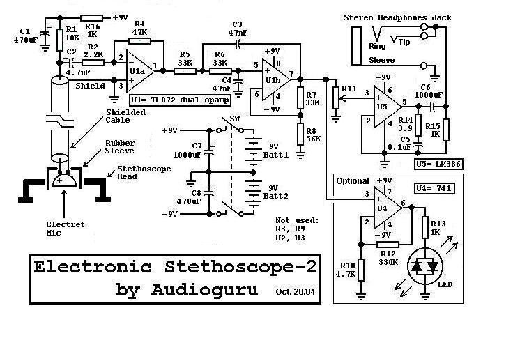
U1a operates as a low-noise microphone preamp. Its gain is only about 3.9 because the high output impedance of the drain of the FET inside the electret microphone causes U1as effective input resistor to be about 12.2K. C2 has a fairly high value in order to pass very low frequency (about 20 to 30Hz) heartbeat sounds.
U1b operates as a low-noise Sallen and Key, Butterworth low-pass-filter with a cutoff frequency of about 103Hz. R7 and R8 provide a gain of about 1.6 and allow the use of equal values for C3 and C4 but still producing a sharp Butterworth response. The rolloff rate is 12dB/octave. C3 and C4 can be reduced to 4.7nF to increase the cutoff frequency to 1KHz to hear respiratory or mechanical (automobile engine) sounds.
The U4 circuit is optional and has a gain of 71 to drive the bi-colour LED.
U5 is a 1/4W power amplifier IC with built-in biasing and inputs that are referred to ground. It has a gain of 20. It can drive any type of headphones including low impedance (8 ohms) ones.
| Part |
Total Qty.
Description
R1110K 1/4W Resistor R212.2K 1/4W Resistor R3, R90Not used R4147K 1/4W Resistor R5, R6, R7333K 1/4W Resistor R8156K 1/4W Resistor R1014.7K 1/4W Resistor R1112.2K to 10K audio-taper (logarithmic) volume control R121330K 1/4W Resistor R13, R15, R1631K 1/4W Resistor R1413.9 Ohm 1/4W Resistor C1, C82470uF/16V Electrolytic Capacitor C214.7uF/16V Electrolytic Capacitor C3, C430.047uF/50V Metalized plastic-film Capacitor C510.1uF/50V Ceramic disc Capacitor C6, C721000uF/16V Electrolytic Capacitor U1
U2, U3
U4
U51
0
1
1TL072 Low-noise, dual opamp
Not used
741 opamp
LM386 1/4W power amp
MIC1Two-wire Electret Microphone J111/8″ Stereo Headphones Jack LED1Red/green 2-wire LED Batt1, Batt229V Alkaline Battery SW12-pole, single throw Power Switch Misc.1Stethoscope head or jar lid, Rubber Sleeve for microphone.
Assembly
- Assemble the circuit using Veroboard (stripboard) or a PCB.
- Use a shielded cable for the microphone as shown on the schematic.
- Fasten the microphone to the stethoscope head with a rubber isolating sleeve or use a short piece of rubber tubing on its nipple. A thick jar lid can be used as a stethoscope head. The microphone must be spaced away from the skin but the stethoscope head must be pressed to the skin, sealing the microphone from background noises and avoiding acoustical feedback with your headphones.
- The microphone/stethoscope head must not be moved while listening to heartbeats to avoid friction noises.
- Protect your hearing. Keep the microphone away from your headphones to avoid acoustical feedback.


Hi, I assembled your circuit. it is working good first 2-3 sec. then it is producing noise.how can ı solve this noise problem?