

iButton electronic lock
- Leonid Ridiko,Victor Lapitskiy
- wubblick@yahoo.com
- 23.489 Views
- advanced
- Non tested
- 0 Likes

Fig.1 Schematic diagram of iButton electronic lock
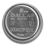
Since iButton DS1990A introduced in market from Dallas Semiconductor (MAXIM), it has been used in many applications concerning security, access control systems etc. In this project we will use iButton as a key to an electronic lock. This electronic lock can use many different kinds of iButtons and can store up to 9 different keys. One of the keys is the master key and is permanent stored in memory. With the use of master key we can add or remove slave keys.
This electronic lock can be used with any type of iButtons you may already have, since the only thing needed is the internal serial number, that’s different for every iButton. The command used to read the serial number is the same for all iButtons. The iButton family code that goes with every iButton, can be anything and is calculated as part of the whole serial number. We must also notice that DS1990A series iButtons are the cheapest.
![]()
This electronic lock designed to work stand-alone and it’s easy to construct. What the user sees (outside of the door for example) is a iButton socket and a led. From inside the door, we can open it using a simple push button. For the actual lock of the door a solenoid and a bold are used. Solenoid must be rated at 12Vdc. iButtons serial numbers stored in memory can be removed and updated when needed. One master key is used to manage the rest of them. Totally a number of 9 different keys can be stored in memory.
Schematic diagram is shown at figure 1. The circuit is build around an Atmel AT89C2051(U1) microcontroller. The port 1 (P1) of mcu is used to connect a 7-segment common anode led display. This led display will be used on the programming of additional keys. For the same reason a push-button labelled SB1 is connected on P.3.7. Storage of iButtons serial numbers is done on a 24C02 EEPROM (U3). It is connected on P3.4 (SDA) and P3.5 (SCL) of U1. The external iButton socked is connected on port P3.3 via XP2 pin array. The rest of components VD4, R3, VD5 and VD6 are used for protection of mcu ports. One pull-up resistor R4 is used as required from 1-wire protocol. An additional iButton socket is connected parallel with the predefined at pins XS1. This one is used for programming the keys. The door OPEN button is connected on P3.2 through XP1 connector, using the same protection components as above. The solenoid that does the lock is connected on XT1 connector. Solenoid is controlled from a power MOSFET IRF540 (VT3). Diode VD7 is added to protect MOSFET from voltage strikes due to solenoid inductance. Transistor VT3 is controlled from VT2, which reverses the logic state that’s appears on P3.0, so on VT3 we have output 0V and 12V. This additional transistor is useful as it translates the mcu logic levels to 0V and 12V, capable to drive the solenoid.
A led is used to indicate the state of the electronic lock, which is controlled from the same pin as the solenoid, using transistor TV1. This led is connected to the board using the same pin array XP2. But we need to ensure that the circuit will always work without supervision. For that reason we added ADM1232 (U2) that does the mcu reset pin control. This chip have a counter and voltage test circuits inside it. On pin P3.1 mcu produces pulses when it works right. If for a reason mcu freeze then U2 send it a reset pulse and work is resumed.
This electronic lock has it’s own power supply on board, consisting of transformer T1, bridge rectifier VD9-VD12 and voltage regulator U4. As power backup an array of 10 AA batteries is used (BT1-BT10). Total capacity is 800mAH. When the circuit is connected on main voltage the battery pack is charged via R10 with a current of 20mA. This current is equal to 0.025C (where C is the batteries capacity) and that’s a very small current depending on total capacity. That’s put the battery on a steady charge to compensate losses among time and no charge completion detection is needed. That can be done as the excess energy is consumed in heat, that can not harm batteries as its low.
Overall board dimensions are 150х100х60mm. The most components are placed on the board, including the transformer. Batteries are placed on battery holders. In the place of AA batteries we could use a 12V sealed Lead – Acid battery. External components are connected on board with 2 or 3 pin connectors. Part numbers HG1, SB1and XS1 are used only in programming mode so can be placed inside the plastic enclosure. Led VD3 can be placed on the face of enclosure, to indicate proper powering of board. A connection diagram is show on figure 2.
Fig.2 Connection diagram
When the door goes open, a 3 sec pulse is triggering the solenoid. When we press the door open button the door remains open as long as we push it.
The electronic lock can register 9 keys, plus one master key. Master’s serial number is stored inside mcu. The rest of keys are stored on the external memory under slot 1 to 9. To add or remove a new key you should have the master key. Also master key can be used to open the door.
Fig. 3 Programming steps for adding a new key
To add a new key, the following steps should followed:
- Press programming button.
- Led displays letter «P» that indicated you entered programming mode
- Touch the master button in socket.
- Led displays number «1». That’s the current selected slot in memory.
- Push the programming button to select a different programming slot for your new key.
- Touch the new key to the socket.
- The number on led display blinks, indicating ready to program.
- Touch again the new key to confirm registration to memory.
- If successfully registered the display stops blinking.
- After 5 seconds, the program exits from programming mode.
The programming procedure to register a new key is displayed schematically on figure 3.
If you want to register more keys, then from step 9 you can go directly to step 5. These steps can be revised as many times as you like.
If after step 7, you find out that you selected wrong slot number and you don’t want to loose that key, press programming button or just wait 5 seconds. When you press the button the slot number increases by one and memory hasn’t changed yet. If you wait 5 seconds, programming mode will exit and nothing is going to register in memory. Generally in any programming step, you can wait 5 second to exit programming mode.
To remove an already registered key, you follow an almost same procedure, using only the master key. Basically, it’s like registering the master key on the memory slot you would like to erase. This procedure is shown on figure 4.
Fig.4 Programming steps for removing a key.
During programming mode, the door will only open with the press of the OPEN button. Also, because the two iButton sockets are connected in parallel, you should avoid simultaneous touch of keys on both sockets.
Master’s key serial number is stored on mcu’s program memory, beginning from address 2FDH. The length of serial number is 8 bytes. The serial must be equal that is printed on top the iButton case, reading from left to right. On memory address 2FDH the control byte is registered, then on address 2FEH – 303H the next six bytes are registered, beginning with most significant byte. Finally the family code byte is stored on address 304H. For example a complete serial code should look like: 67 00 00 02 D6 85 26 01
The software block diagram shows on figure 5. The program starts, asking if a key has entered. If a key is entered, then it goes on reading the internal serial number. The next step is to check if this is the master key or another key already registered in memory. If the key is verified then the door is opened. Also the OPEN push button is checked, and if it’s pressed the door opens.
Fig.5 Software block diagram
For the programming mode there exists two subprograms: PROGT and PROGS, whose block diagrams show in figure 6. The first is called when the serial number is read, in the programming phase and the second is called when the programming button is pressed. Programming of a new key is completed in three phases. When we press the programming button, we enter the programming mode. In this state the led displays «P» and the serial number of the key is checked to see if this is the master key, because this key is required to proceed on programming steps.
If this is the master key, we proceed on phase 2. Now, led is displaying the number of current selected memory slot, changing by pressing programming button. If we touch the key again, then it is registering on memory and we pass to phase 3. If we touch another key, this is also registered and we pass to phase 2. With the press of the button, we pass on phase 2 without registering any key.
If we don’t touch anything in a period of 5 seconds, the program exits from programming mode. Block diagrams of figure 5 and 6 are simplified, but they give as an overall sense of program functionality.
It’s upon your desire to extend the capabilities of this program, as it’s open source, to fit your special needs.
Fig.6 Programming mode subprograms block diagrams


Excellent!!! Great work !!! I admire the design, narrative and block diagrams.