

Programmable Home Security Alarm System
- Dilshan R Jayakody
- jayakody2000lk@gmail.com
- 49.724 Views
- advanced
- Tested
- 0 Likes

Introduction
In this project we design low cost high performance programmable home security system and there is no need to contact a company like Safemart home security for setup. This system uses a few LDR’s as input sensors. When above sensor(s) get triggered system may dial the user specified phone number (using build-in DTMF generator) and activate the high power audio alarm and lights. All the parameters of DTMF generator, audio alarm and light interface are programmed through the RS232 serial interface.
Current firmware of this system presents interactive control system through the RS232 interface. This control system consist with the menu driven configuration options, self tests, system report generators, etc. This system also contain 5W (with 4Ω speaker) audio alarm with three selectable tone configurations, which include Police siren, Fire engine siren and Ambulance siren.
System Features
- Touch tone phone dialing interface
- 5W High powerful audio alarm
- 2 sensor interface with separate sensitivity adjustments
- Programmed through the RS232 interface
- Build-In intelligent light ON/OFF switch
Integrated Circuits
This system uses a Microchip’s PIC16F877A as a main controller, LM339 as sensor interface, UM3561 as a tone generator and μPC2002 as a speaker driver (audio amplifier). LM7805, LM7812 and LM317 voltage regulators are used to obtain +5V, +12V and +3V respectively.
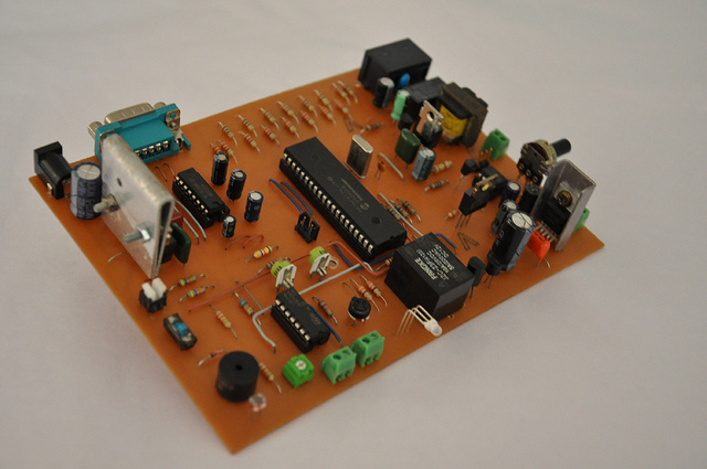
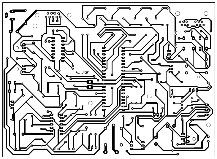
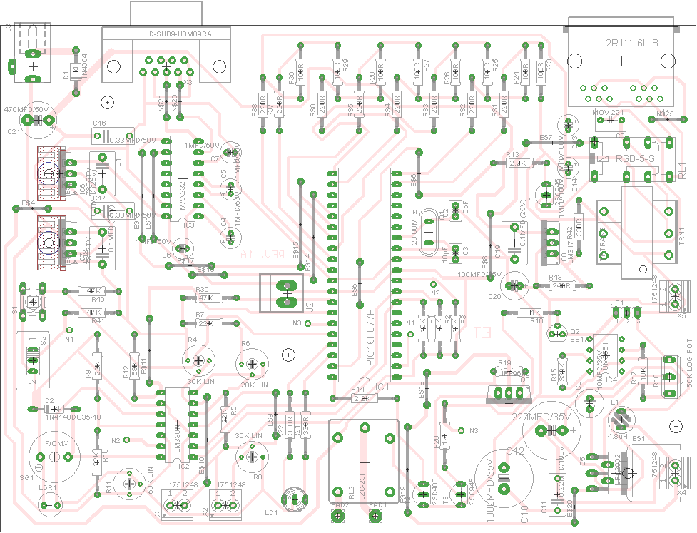
Assembly
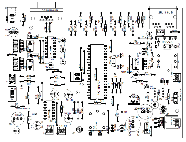
The PCB design given with this article makes the assembly much simpler. As PCB contain 230V AC main lines care must be taken while assembling the circuit. As shown in the fig.1 all the photoelectric sensors, some of the switches and alarm speaker are connected with the circuit through the connector bars.
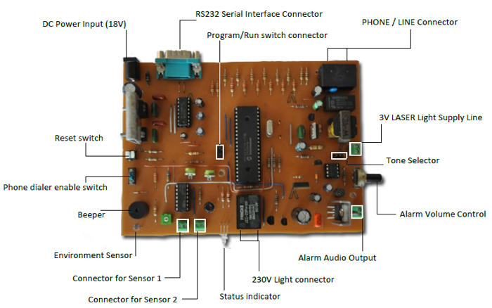
External connectors and controls
DC Power input : Attach DC power supply with 18V – 25V (2A Max.) output.
RS232 Connector : Connect RS232 serial cable to the port to configure the system. Do not use RS232 Null Modem cable with this port.
PHONE/LINE connector : Attach standard RJ12/RJ11 telephone cable connector to this port. One port is need to use with the phone line and remaining port is for the phone (and it is optional).
3V LASER supply : 3V supply line for LASER diode assembly.
Connectors for Sensor 1/2 : Attach high sensitive LDRs for these ports. To get the maximum sensitivity it is recommended to use EG&G VACTEC LDRs.
Status Indicator : Indicate run, program and sensor trigger modes.
Reset Switch : Press this button to reset entire alarm system. This button enable only when the audible alarm get activated. It is not possible to use this function at the phone dialing/ringer states.
Phone dialer enable switch : Turn on this switch to enable the phone dialing feature of this system. Environment Sensor : In-circuit LDR to detect light conditions of the environment.
Alarm Volume Control : Use this to control the output power (volume) of the audible alarm.
230V Light connector : Attach 230V AC light (or related peripheral) to these terminals.
Tone Selector : Configure the master alarm tone from this jumper as follows,
1-2 : Fire Engine Siren
2-3 : Ambulance Siren
Open : Police Siren
(Do not connect jumper terminal 1-3, this combination may permanently damage the entire system) Beeper : Produce beeps (e.g: at the input error, etc.)
Program / Run Switch connector : Attach switch to this header to select Program or Run mode.
Alarm Audio Output : Attach 8Ω (8W) or 4Ω (10W) speaker to this connector.
Calibration and Testing
Once everything is assembled take following steps to calibrate the system,
- Remove IC1, IC2, IC3 and IC4 from the IC bases.
- Apply 18V ( to 22V Max.) DC source to the power connector (J3).
- Check the voltage between Pin12 (GND) and Pin3 of IC2. It need to be 4.8V – 5.1V DC.
- Check the voltage between GND and E$4 jumper. It need to be 11.7V – 12.3V DC.
- Check the voltage between Pin1 and Pin3 (GND) of JP1. It need to be 2.5V – 3.1 V
- If all the above Step 3, 4 and 5 are correct, disconnect the power supply and insert IC1, IC2, IC3 and IC4 in to the appropriate IC bases. Attach suitable speaker to the X4 and connect RS232 cable to the system.
- Close the jumper J2 (Program Mode) and power on the system.
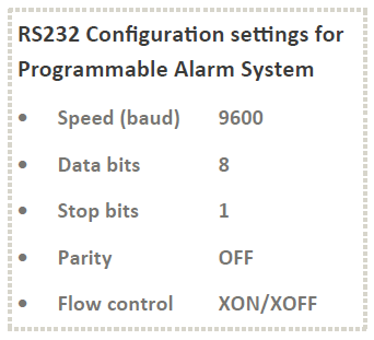
- Download and install PuTTY on to the target computer and setup the “Serial” connection with 9600 baud rate (see Fig. 3).
- Press “2” and enter into the “Parameter Setup” mode. Configure all the parameter options with the appropriate settings.
- Attach phone line to the PHONE/LINE connector and fix photoelectric LDR sensors to the X1 andX2 connectors.
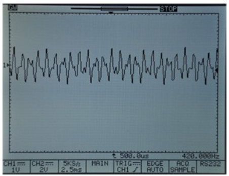
DTMF output generated by the system at the testing stages. (Test points : TRN1 input terminals) - Press “3” and execute “Self Test”.
- Adjust R4*, R6* and R8* preset controls, if the sensors are not trigged as expected.
- Adjust R11 preset to control the “Day” and “Night” mode detection.
- Open the Jumper J2 and press 5 to return to the Run mode.
- Shutdown the power supply and disconnect the RS232 cable.
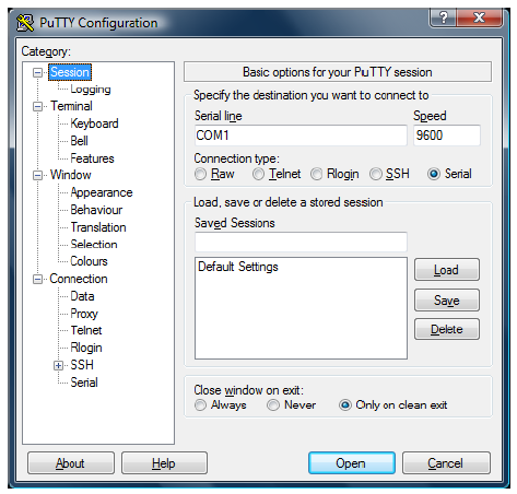
Fig.3 – PuTTY configuration setup for Programmable Home Security Alarm System
* R6 – X1 sensor sensitivity, R8 – X2 sensor sensitivity, R4 – sensor gain controller (Common mode)
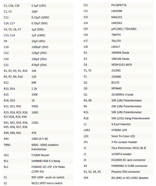
Parts
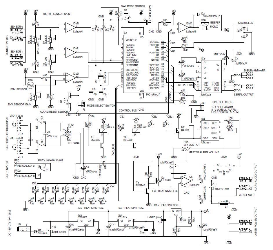
Schematic

PCB


What type of sensors I can connect to this device?
In this project LDR sensors are used as input sensors.
Is it possible to connect any other sensors like gas sensor or motion sensor?
The sensor input of this alarm are intended to be used with resistive sensors, like LDRs and touch sensors as the input is feed to an OPAMP comparator that compares the input voltage (from the sensor) to a predefined voltage and the logical output of the OPAMP is feed to the microcontroller. So if your sensor has a logic high/low you may discard the input OPAMP circuit and connect them directly to microcontroller assuming that their output is 5V.
Would i be able to use this for a class project at school. What is the difficulty range of the kit as far as building and programming the kit. Along with what sensors can be used to detect/ set off the system.
How to buy Programmable Home Security Alarm System kit?
We are sorry, we don’t sell kits or assembled boards of this project.