


Tutorial on the Design & Implementation of an FPGA RGB LED Matrix Driver
In this episode Shahriar and Timo demonstrate the design methodology of an FPGA based 32×32 RGB LED matrix driver. Timo has kindly devoted some of his time to describe the block diagram and the thought process which goes into designing this type of FPGA display driver. The various components of the overall system (PLL, UART, and Display Controller) are shown along with the simulation data. The outputs of the Spartan-6 FPGA board are then measured using a Keysight S-Series oscilloscope. The design of the RGB matrix is also demonstrated using a custom clock interface sent wirelessly to the unit via Bluetooth.
Tutorial on the Design & Implementation of an FPGA RGB LED Matrix Driver – [Link]
RELATED POSTS
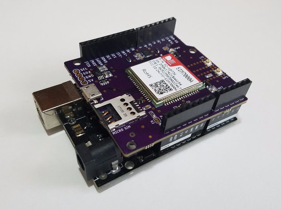 13 December, 2017 Open-Source NB-IoT Shield for Arduino
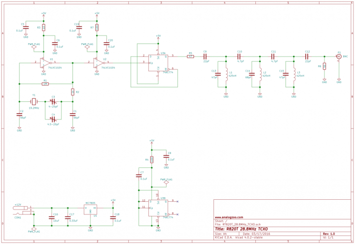 4 April, 2016 28.8MHz TCXO with +-1ppm Stability
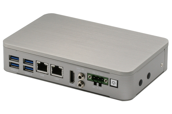 25 September, 2018 Work Faster, Work Smarter, Work Safer with the BOXER-6405 Edge AI Smart Factory System
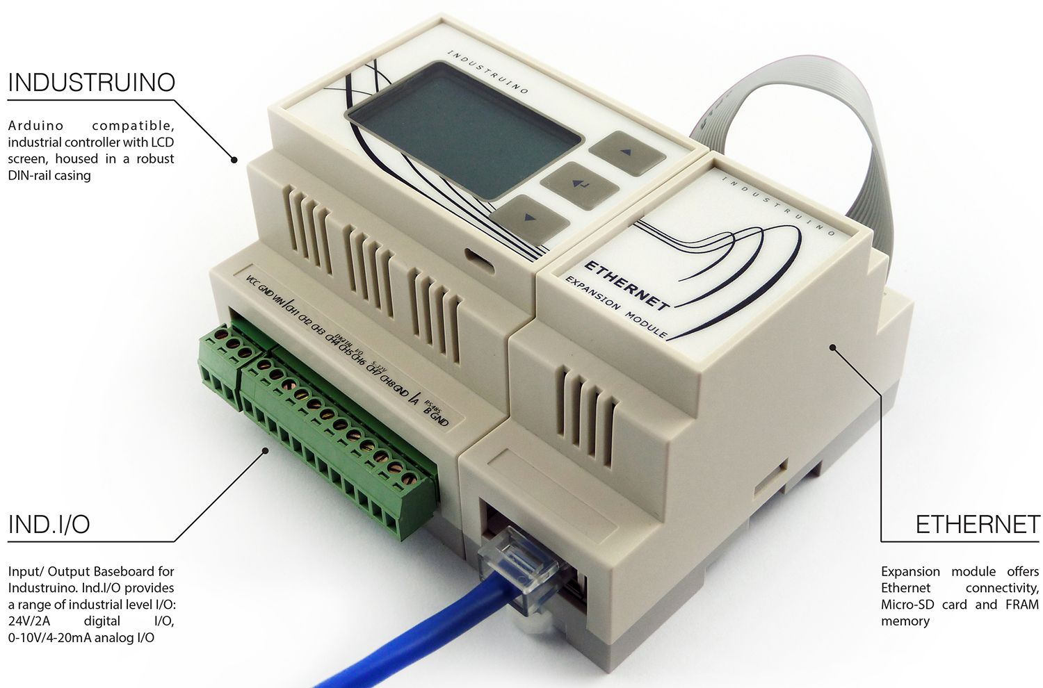 22 September, 2015 Industruino – Arduino compatible industrial controller
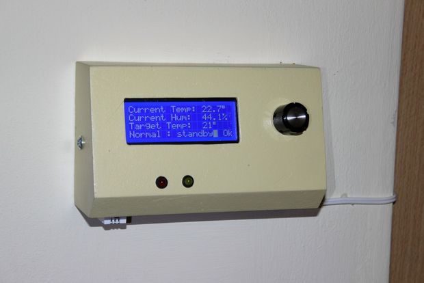 17 January, 2016 Home Thermostat With Arduino and LCD
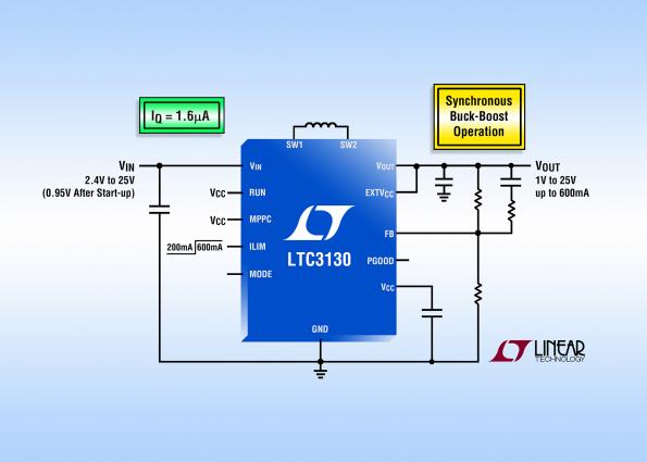 26 August, 2016 25V, 600 mA buck-boost DC/DC with 1.6 µA Iq
Subscribe
Login
0 Comments


