


 With Arduino")
Most of hardware developers have used a temperature sensor in one or more of theirs projects. There are many types of temperature sensors, such as LM35, thermistors, and resistance thermometers. These types differ in response speed, temperature ranges, accuracy, and other factors.
Resistance thermometer, which also known as Resistance Temperature Detector (RTD), is a device used to measure temperature by changing its resistance depending on the surrounding temperature. It has a slow response time but provides accurate values. A RTD consists of a length of fine wire wrapped around a ceramic or glass core. The RTD wire is a pure material, typically platinum, nickel, or copper.
This instructable shows a full guide of how to use a RTD with Arduino, it uses a two wire PT100 RTD, an Arduino, 3 LM741 operational amplifiers, and resistors.
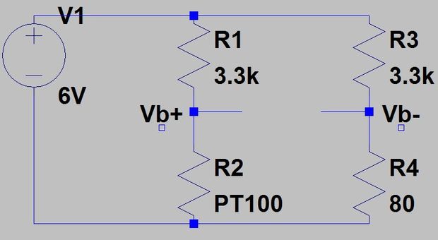
The first part of the circuit is about converting the resistance change of PT100 to a voltage change so the Arduino can read it. This operation can be done using a voltage divider, but for a specific range of 80 to 150 ohms (-51.85 to 129.87 degrees C) the divider has a DC offset which will decrease the sensitivity when amplifying this voltage.
To solve this issue you can use a Wheatstone Bridge, an electrical circuit used to measure an unknown electrical resistance by balancing two legs of a bridge circuit, to get rid of the DC offset and to increase output sensitivity. The values of Wheatstone resistors had chosen to limit current flow and to increase linearity of the output.
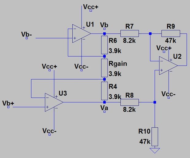
The output of the previous circuit is calculated by subtracting Vb+ and Vb- and then amplifying the result to be readable. To do this you need a differential amplifier, but there are two problems will occur when connecting this amplifier to the output of the bridge: the loading effect and changing the gain.
The loading effect means that the input resistors into the amplifier are affecting the voltage drop across the PT100 and changing the results. Changing the gain of the amp requires you to change at least two resistors, so having two potentiometers which have the same value will be annoying.
This problems had been solved by an instrumentation amplifier which acts as a buffer amplifier to separate the two halves of the circuit, the bridge and amplification, as well allows amplifying the input by changing just one potentiometer.
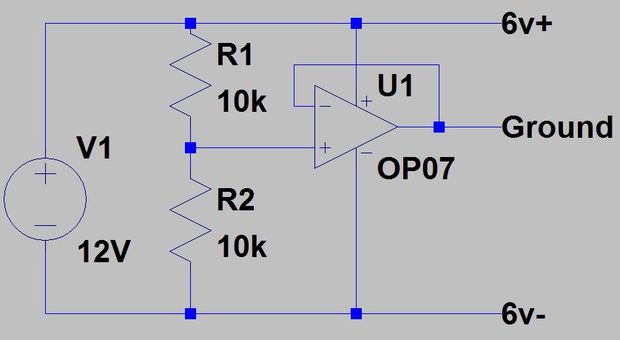
The last step is powering the circuit. As shown in the past circuit, there are Vcc+ and the Vcc-, because it needs both positive and negative voltage to function properly. These voltages can be generated using only one 12V power source, its circuit uses a buffer amplifier of gain 1 to create a virtual ground by passing half the supply voltage through the buffer amp which will act as the ground. Then the 12V will work as the +6V and the actual GND terminal will be -6V.
The full circuit was designed using Autodesk Circuits.io, a platform that lets you create circuits on breadboard, edit circuit diagram and pcb diagram, and it also lets you simulate the circuit from the breadboard. You can even program an Arduino and connect it in the breadboard mode. If you want to duplicate the circuit and add your own values, just edit the design here.
This project is open source, you can find a detailed description of how the circuit works, circuits diagrams, equations, and source code at the project page at Instructables.com.
RELATED POSTS
 30 July, 2018 Particle sensor with LoRa
 26 October, 2022 Meet the Modern Mini CB-11 Waterproof Doorbell from Avantek
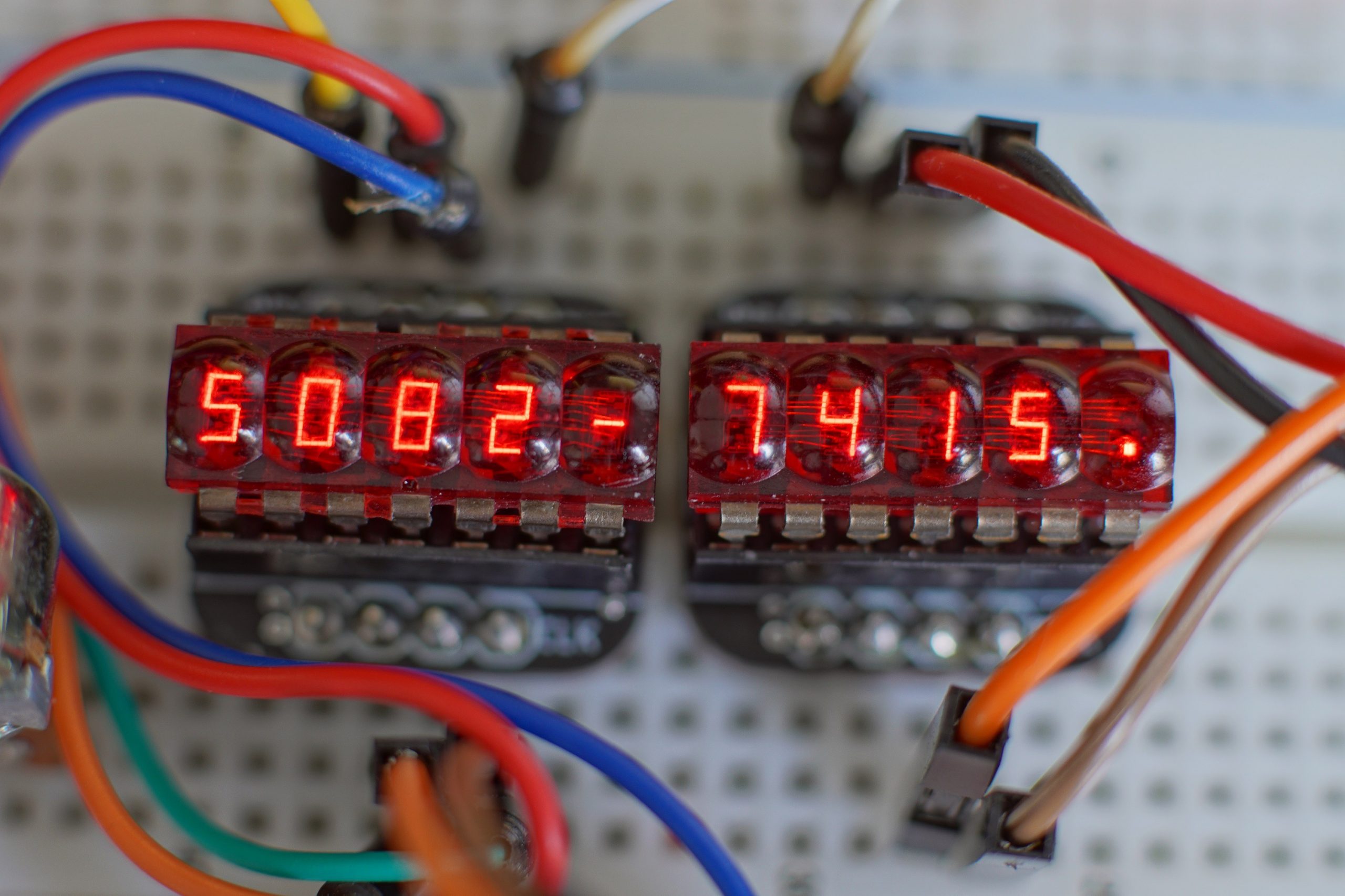 12 June, 2019 HP 5082-74xx 7-segment display revived
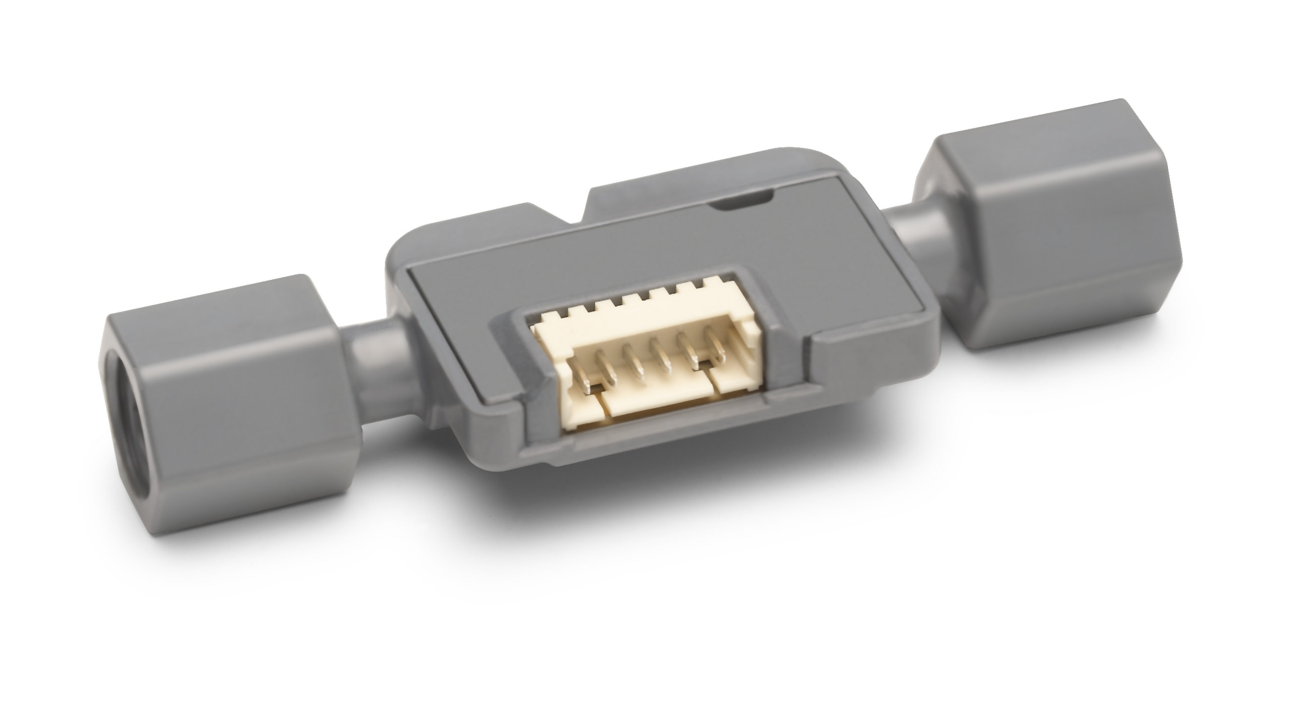 7 November, 2018 Sensirion Announces Its New Liquid Flow Sensor – SLF3S-1300F
 18 September, 2019 Wi-Fi 6 milestone reached
 18 November, 2020 LD49100 Low Quiescent Voltage Regulator


