

Boolean Algebra Examples
- Muhammad Shahid
- m_shahid@live.co.uk
- 1.787 Views
- 0 Comments
- 0 Likes

Boolean Algebra Examples
In the previous articles, it has been shown that the digital logic gate and digital circuit can be represented by a Boolean expression and a truth table. A Boolean expression consists of a number of variables representing inputs and an output which is usually represented by a “Q”. The inputs and outputs have Boolean logic data type i.e. either “0” or “1”. The Truth Table lists the output of the logic gate or digital circuit against all the possible combinations of inputs. Using the Boolean algebra and laws of Boolean algebra, the complex digital logic circuits can be reduced.
The identification and replacement of unnecessary logic gates lead to saving space, cost and power. The reduction process of a complex digital logic circuit can have multiple paths depending on the application of laws and theorems etc. However, the reduction paths should yield a similar and simplest circuit if Boolean algebra and laws are applied correctly.
In this article, a few digital logic circuits are reduced using the application of Boolean algebra and laws. The reduction process has been explained and truth table(s) are also given to aid the explanation and reduction process.
Boolean Algebra Example No. 1
In the following figure, a digital logic circuit is shown. The circuit consists of three AND gates and two OR gates. A total of five gates are required to produce the desired logic function. In this example, the desired logic function is reduced by applying Boolean Algebra Laws and Theorems.
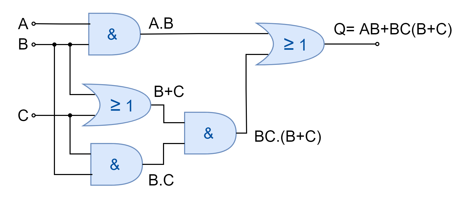
The steps involved in the reduction of Boolean expression are as follow:
AB + BC(B+C)
Applying Distributive Law
AB + BBC + BCC
Applying Identity Law (AA=A) to 2nd and 3rd terms
AB + BC + BC
Applying Identity Law (A + A = A) to 2nd and 3rd terms
AB + BC
Taking out common B
B(A+C)
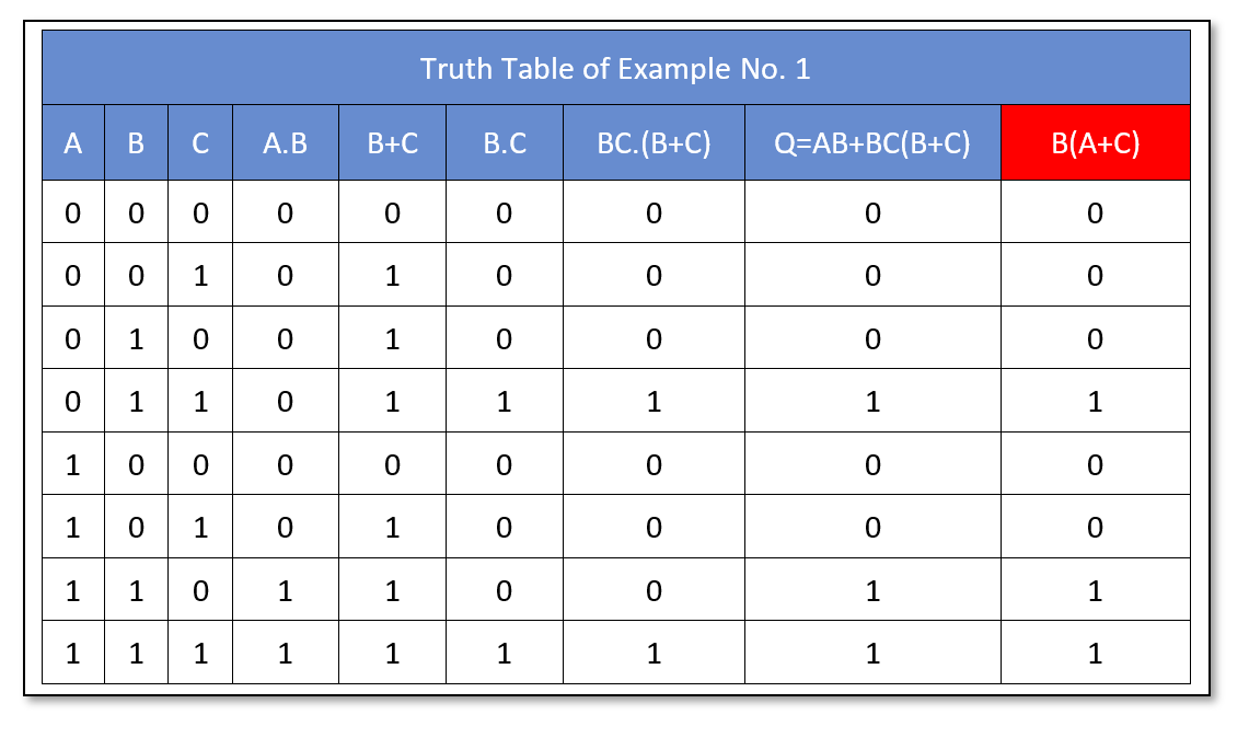
The reduced expression B(A+C) produces the same logical output as of original expression. The truth table of the original Boolean expression as well as of reduced expression (red) is shown below:
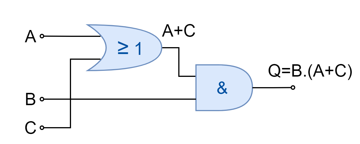
The reduced expression requires only two logic gates i.e. AND, and OR gates. A reduction in three gates has been achieved by applying Boolean Algebra Laws to a complex expression. The simplified logic circuit diagram is shown in the following figure.
Boolean Algebra Example No. 2
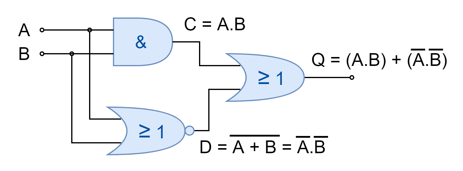
In the following figure, another digital logic circuit is shown.
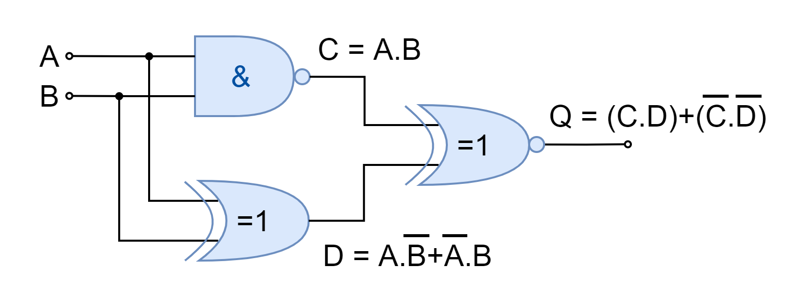
The given digital circuit consists of a total of three logic gates i.e. NAND, XOR, and XNOR. This digital circuit is being reduced by constructing a truth table. The truth table constructed is then analyzed to identify single logic to replace the output. The 2-input gives four combinations and is easy to construct. For such kinds of digital circuits, the truth table technique is more feasible. The following table is constructed easily by knowing the truth table of the individual gates. The output “C”, “D”, and “Q” corresponds to NAND, XOR, and XNOR, respectively. The outputs “C” and “D” become the input of the XNOR gate.
The truth table generated is shown below:
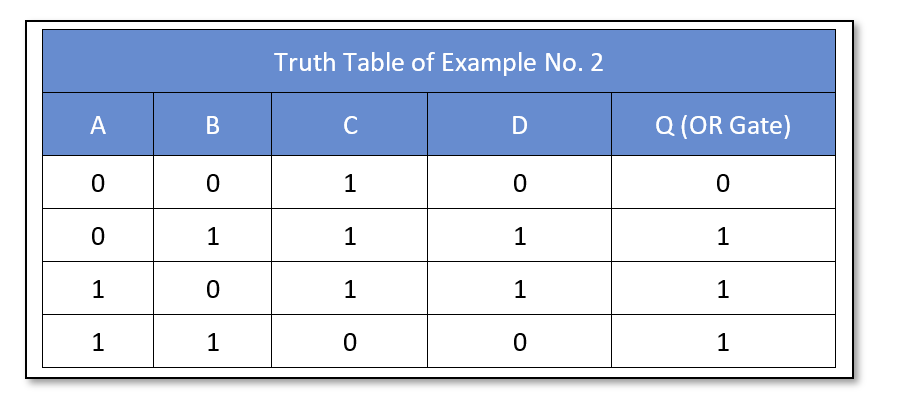
The output of the digital logic circuit is “HIGH” when any of the inputs “A” or “B” is “HIGH”. This expression or output is given by a digital OR gate. Hence, the given three logic gate circuit can be reduced to a single OR gate with inputs “A” and “B”. The simplified logic circuit having the same output as the original digital circuit is shown below:

Boolean Algebra Example No. 3
In the following figure, another logic circuit is shown.
The digital logic circuit comprises three logic gates i.e. AND, NOR, and OR. The output of the NOR is converted to the product of inversed individual input. The final output of the OR gate which is the function of the whole logic circuit comes to be equivalent to the function of XNOR logic. Hence, the given three gates digital logic circuit can be replaced by a single gate of Exclusive-NOR gate.
The truth table technique has also been adopted to obtain a single gate equivalent. The truth table has been constructed and shown below:
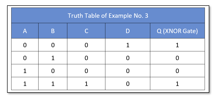
The circuit’s final output “Q” is equivalent to Exclusive-NOR gate output. The truth table also identifies the Exclusive-NOR as a single-stage equivalent of the given logic circuit. The Exclusive-NOR (XNOR) gate with two-inputs “A” and “B” has shown in the following figure.

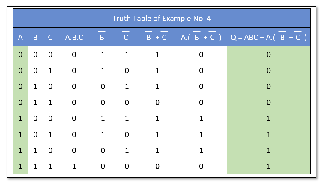
Boolean Algebra Example No. 4
In the final example, a more complex digital logic circuit has simplified which consists of six logic gates. The logic circuit to be reduced has been shown below.
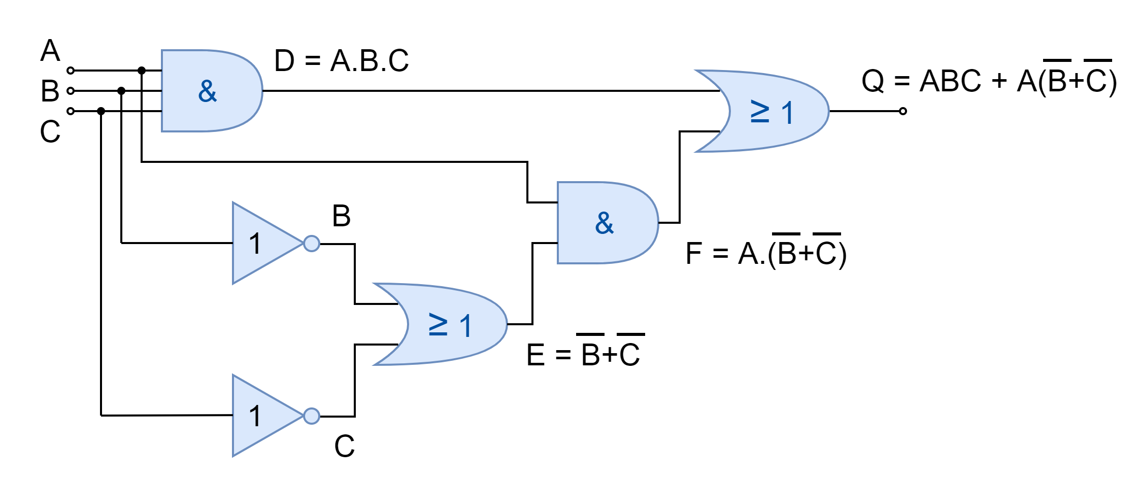
Using the digital logic circuit, Boolean expression at each stage has been derived and a truth table has been constructed using these Boolean expressions against each possible combination of input. The final output “Q” of the logic circuit has been analyzed which is equivalent to input “A”. A single wire from input “A” to output “Q” or a Buffer can replace this six-gate logic circuit. The truth table constructed has been shown below:
The Boolean expression of the given logic circuit has also been reduced below using Boolean algebra laws and theorems.
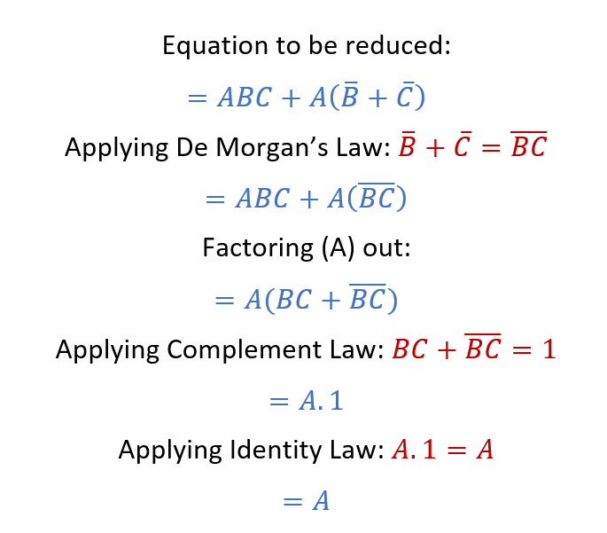
The above solution also reveals that the given logic circuit simplifies to have only a Buffer with input “A”. The reduced logic circuit has been shown below.

The above examples show the ways to obtain a cost-effective, compact, and power-efficient solution. Similar, advantages can be obtained by adapting the same techniques to other digital logic circuits.
Conclusion
- The complex digital circuit may be reduced to the simple logic circuit using Boolean Algebra Laws and Theorems.
- The digital circuits with few inputs can be reduced by constructing the table and identifying the output with equivalent single gate logic or input.
Please follow and like us:
Subscribe
Login
0 Comments


