

Bypass Diodes in Solar Panels
- Muhammad Shahid
- m_shahid@live.co.uk
- 1.581 Views
- 0 Comments
- 0 Likes

Bypass Diodes in Solar Panels
As the name suggests, the bypass diodes allow the current to bypass a device or equipment under certain conditions. The conditions of bypass may include the faulty or open-circuited device etc. In solar panels, the bypass diodes come into action when they become faulty or open-circuited or in other words become underrated compared to other adjacent solar panels.
The bypass diodes are connected in reverse-parallel configuration with the solar panel. The solar cells or panels are connected in series to ascertain a voltage level. The bypass diodes installed in reverse-parallel configuration to each cell allow current supply in case any of the adjacent solar cells becomes unavailable. The reverse-parallel configuration does not affect the output of the solar cell and the bypass diode is connected to a group of cells rather connecting across each cell which becomes costly.
Construction and Working Principle of Solar Cell
The solar cell is basically a semiconductor device and has layers of semiconductor materials. Just like a PN junction diode, the solar cell is made of P-type and N-type layers. These layers are formed by doping with materials having excess or deficiency of electrons. The layer having excess electrons is made of N-type semiconductor and the layer having deficiency of electrons or excess of holes is made of P-type semiconductor. The combination of these layers enables the silicon wafer to become light-sensitive and produces electric energy across its terminals upon striking of photons/ light. A number of such silicon wafers are connected in a series-parallel combination to obtain a cell of significant open-circuit voltage and this comprises a solar cell.
The solar cells are connected to each other through metallic strips to guide the flow of current towards the output. The light falling upon cells gives energy to electrons of semiconductor material and free them from atomic bonds. The electrical paths are established using semiconductor materials to collect current from each semiconductor wafer towards output, collectively. The solar cells are connected with each other on the surface facing the Sun. The sun-facing surface is made anti-reflective in order to absorb most of the sunlight falling upon it. The two electrical contacts (+ & -) obtained from the solar panel are either connected to the load or other panels to expand the capacity of the overall solar system. The positive terminal is normally obtained from the front surface and the negative terminal from the back surface of a solar cell.
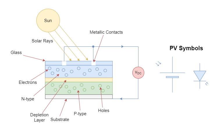
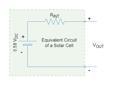
The voltage produced by a single solar cell normally ranges from 0.5 to 0.6 Volts (DC). The voltage produced by a solar cell depends on the construction and configuration of the solar cell. However, the magnitude of the current produced upon connection of load depends majorly on the photons striking on the surface of the solar panel. Normally, the voltage remains nearly constant whereas the current is considered to be proportional to the size of the cell and the intensity of light falling upon it. The solar cells may vary to other connected solar cells due to the manufacturing process and this can be modeled as internal resistance in conjunction with the solar cell. The equivalent model of a solar cell or photovoltaic (PV) cell is shown in the following figure.
Photovoltaic (PV) Characteristics
The photovoltaic solar cells produce DC power when exposed to sunlight. In the absence of load (IOC = 0), the voltage produced is maximum and termed as open-circuit voltage (VOC). The open-circuit voltage (VOC) is normally in the range of 0.5 to 0.6 Volts DC and such a voltage is quite less compared to standard battery voltage i.e. 1.5 Volts. The series connection of multiple cells can increase the open-circuit voltage just like normal batteries.
The maximum current produced by the solar cell is dependent on sunlight absorption. Under certain sunlight exposure, the maximum current is produced upon shorting the terminals and is called short-circuit current (ISC). However, at this operating point, the open-circuit voltage has reduced to zero and, as such, the output voltage is dependent very much on the load current. The output voltage (VO) increases from 0 to VOC as the output current decreases from ISC to 0.
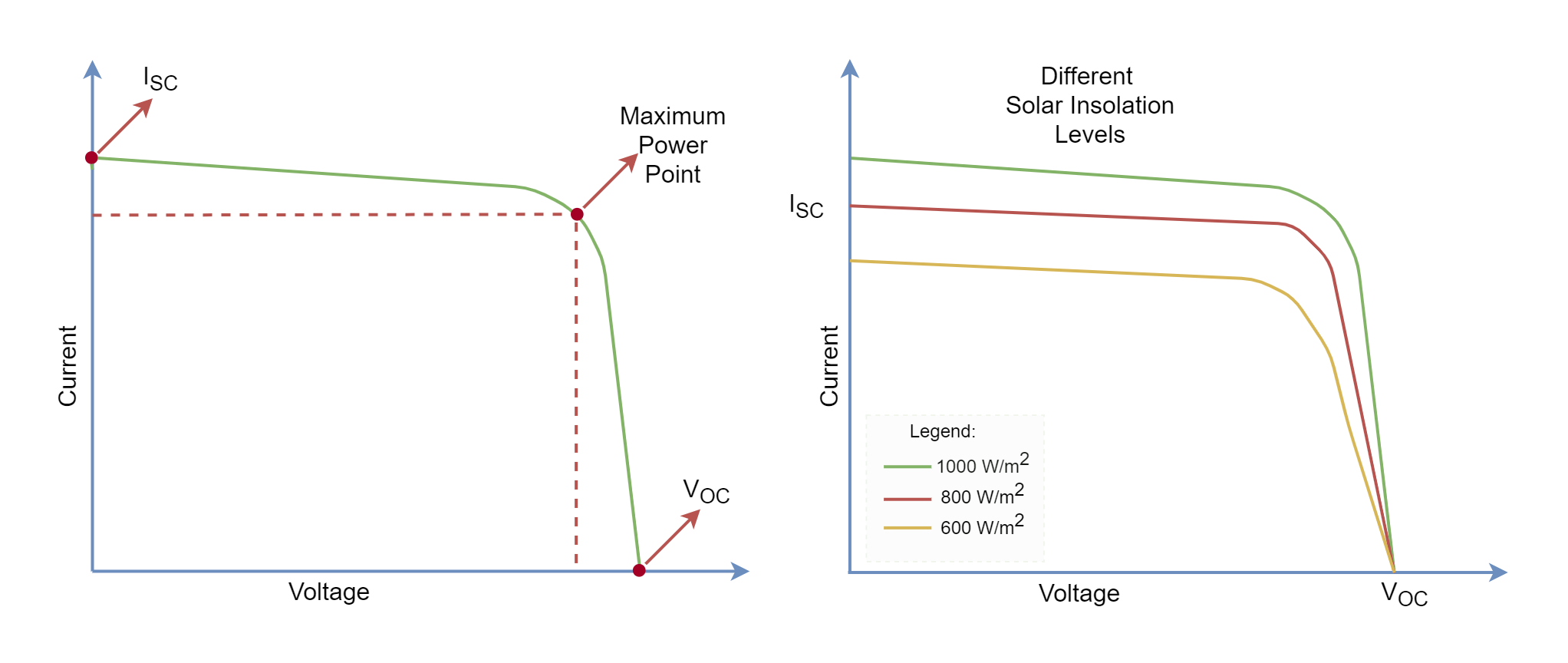
The output current or power is proportional to the intensity of sunlight absorbed by the front surface of the photovoltaic. For example, under cloudy weather, the sunlight striking on the front surface may reduce the output current or power but, still, it may produce a full output voltage. Brighter sunlight, not the temperature, can provide a heavy load current requirement of a load connected to it. However, there exists a maximum limit of the current that can be produced i.e. IMAX which can be delivered to the load and depends majorly on the size of the photovoltaic.
The selection of diodes for the solar cells merely depends on the maximum deliverable current (IMAX) of the photovoltaic. It depends on:
- The surface area of the cell
- Sunlight
- Type of semiconductor used
- The efficiency of conversion into electric current
Usage of Diodes in Photovoltaic Arrays
A photovoltaic array consists of solar panels connected in series and parallel configuration. A series combination helps in attaining a higher open-circuit voltage whilst a parallel combination provides a higher output current. The diode is a unidirectional device which means that it allows the flow of current only in one direction. The blocking diodes used in the series branches allow the branch currents to flow from solar cells/ panels to the output only. In absence of blocking diodes, the branches with higher voltages may contribute/ supply current to low voltage branches causing loss and heating. A damaged cell or partial shading can lead to such a condition. However, blocking diodes block the current flow from other branches to branches with such solar panels.
Bypass Diodes
The bypass diodes are placed in reverse-parallel arrangement with the solar cell or panel. As we know that in the series branch the same current flows through each series element. In a photovoltaic array, a solar panel output may weaken due to deterioration or partial shading which may reduce its current capacity compared to the current produced by efficient and fully exposed to sunlight solar panels. The current produced by efficient and exposed solar panels may overdrive the inefficient solar panel causing overheating and burning. However, a bypass diode becomes forward-biased under such conditions, and current flows through bypass diodes rather than passing through weakened/ damaged solar panels. The bypass diode is placed parallel to the solar panel whereas the blocking diode is placed in series with solar panels.
Similar diodes can be used as bypass or blocking diode but they both serve different purposes and rating of these diodes depend on the IMAX of the series branch.
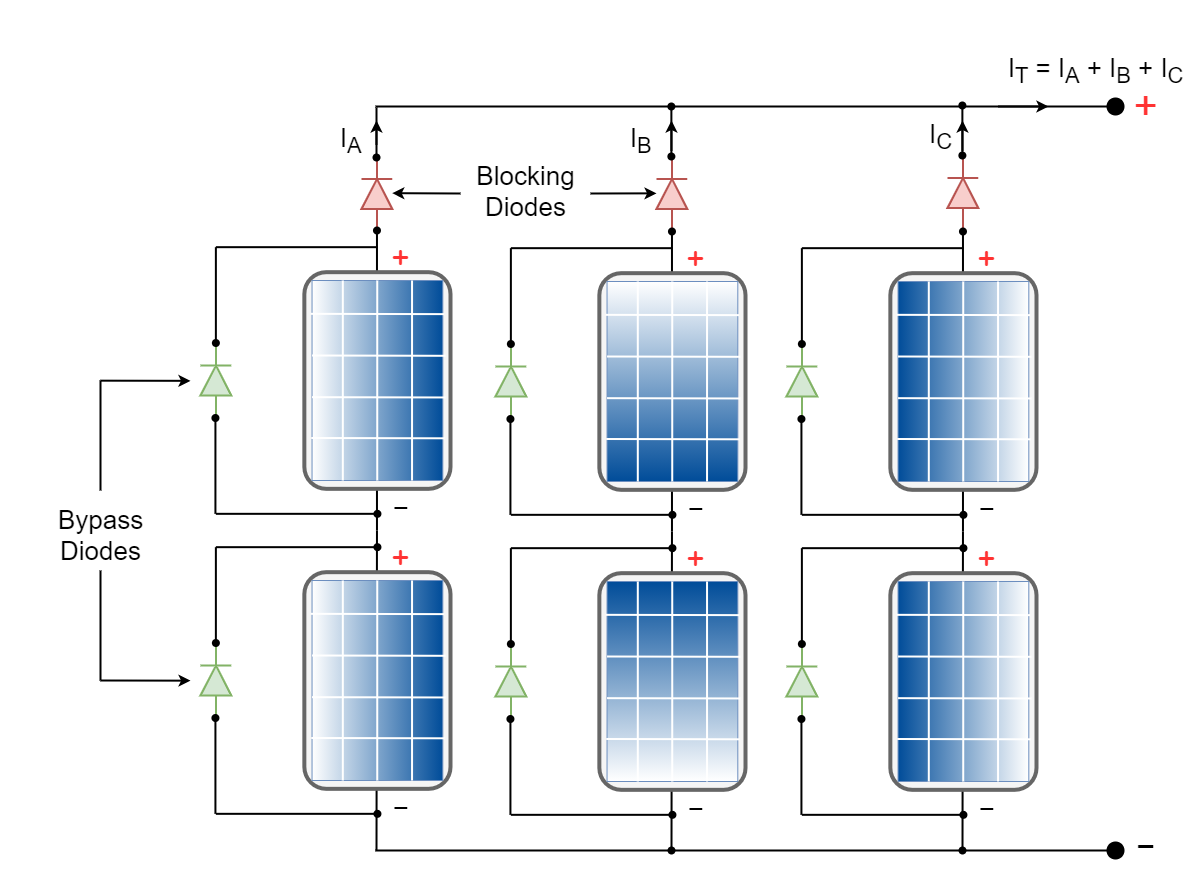
In the above figure, the green color diodes placed in parallel to solar panels are bypass diodes. They serve the purpose of a low resistance path and should have the capability to safely handle the rated current. The red color diodes are blocking or isolation diodes and they ensure that current flows from solar panels to the output only towards the external load. This is to prevent flow of generated current from parallel branches to other branches of the same array which has shaded/ weakened solar panels. Also preventing, drainage of charged batteries by supplying current to a solar array at the night. The blocking diodes are used in each parallel branch of a photovoltaic array.
The conventional diode and Schottky diode can be used as a bypass and blocking diode. Moreover, they are available in a wide range of ratings and can be selected as per photovoltaic array rating. Moreover, the voltage drop of a conventional diode is around 0.7 Volts and of Schottky diode is around 0.4 Volts. The less voltage drop of the Schottky diode makes it more suitable for usage in photovoltaic arrays as bypass and blocking diode. The Schottky diodes cause less voltage drop in a series branch, leading to an efficient array with less power dissipation in blocking diodes.
The manufacturers of photovoltaic panels fabricate the bypass and blocking diodes inside the solar panels to keep the external circuitry simple.
Conclusion
- The solar cells are made of semiconductor layers having an excess of electrons (N-type) and deficiency of electrons (P-type).
- The layers that form the PN junction are sensitive to light/ photons. The light energy is converted into electrical energy by this PN junction forming a solar cell.
- The voltage of a solar cell is very low in the range of 0.5 to 0.6 Volts DC and can be increased by adding multiple solar cells in series and may include parallel branches as well. This form of solar cells in series parallel combination makes a solar panel.
- The current produced by the solar cells is dependent mainly on the light intensity, surface area, and material used in its fabrication.
- The solar arrays are formed by further connecting multiple solar panels in series-parallel combination increasing the covered area with a large number of solar panels.
- The series solar panels may face reduced current when any solar panel gets damaged or becomes partially shaded. In such a case, a bypass diode is used to bypass that weakened solar panel to avoid heating and burning of that solar panel.
- Similarly, the current may flow from other parallel branches to weakened branches. Especially, at night, the charged batteries may start supplying current towards the solar array. In order to prevent this backward current flow in a branch, a blocking diode is used.
- The rating of bypass and blocking diodes depend on the maximum current rating of the solar panel. Both diodes can be the same but serve different purposes.
- The Schottky diode has a less forward voltage drop compared to conventional PN junction diode and is more efficient in solar panels.
- The bypass and blocking diodes are normally internally connected by the manufacturer to keep the design simple.
Please follow and like us:
Subscribe
Login
0 Comments


