

Digital Comparator
- Muhammad Shahid
- m_shahid@live.co.uk
- 10 min
- 802 Views
- 0 Comments
- 0 Likes

Digital Comparator
A Digital Comparator is another type of combinational logic circuit that is used to compare binary digits. It is a very useful logic circuit used in many digital systems to compare values of digital inputs. A binary comparator can be built using only Standard or Basic logic gates i.e. AND, OR, and NOT gates. The digital comparator constructed using these gates is able to compare the digital values present at its input and produces an output, accordingly.
As learned from the previous lecture on Binary Adder, the need for arithmetic operations in binary numbers, just like denary numbers, is of utmost importance and a digital system be capable of performing binary, addition, subtraction, multiplication, division, etc. In addition to these, comparison operation or function is essentially required in each and every digital system. In comparison, binary digits are compared to whether they are equal to each other or which of them is less or greater than the other. This comparison function is accomplished with the help of Boolean Algebra and requires a few logic gates in constructing a Digital Comparator. Digital Comparators are mostly used in Arithmetic Logic Units (ALU) and Analog-to-Digital Converters (ADC) in order to carry out various essential arithmetic functions.
Digital Comparators are classified widely into the following categories:
Identity Comparator
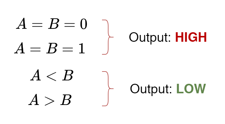
The Identity Comparator compares two inputs and gives output either “HIGH” or “LOW” depending on whether the inputs are equal or not. The Identity Comparator has only “One” output. For example, if two inputs i.e. A & B are compared then Identity Comparator‘s output is set to “HIGH” only when A = B i.e. A = B = 1 or A = B = 0. This is illustrated below:
Magnitude Comparator
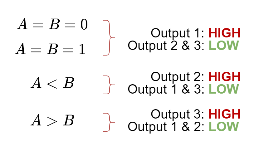
In comparison to Identity Comparator, the Magnitude Comparator has three outputs each respectively set to “HIGH” when binary inputs are: equal, one of them is less, or greater than the other. The functioning is illustrated below:
A magnitude comparator is a very useful circuit to determine if the inputs (A & B) are either: equal, A is greater than B or A is less than B. A 1-bit magnitude comparator compares two single-bit inputs and gives outputs when one of the mentioned conditions is met. For example in an application, a counter is set to alert when a certain count has reached i.e. becomes equal or greater. Here, the comparison between two inputs means the comparison of magnitudes and, therefore, termed Magnitude Comparators.
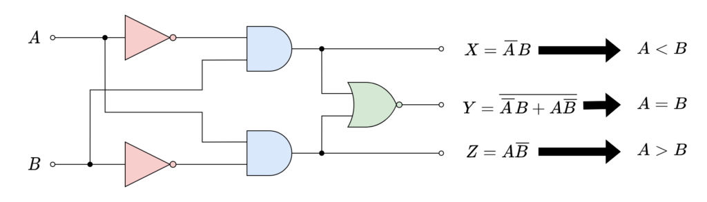
Digital Comparator Circuit
In the following logic diagram, a 1-bit Digital Comparator has been shown. Two single-bit inputs (A & B) are processed through the logic circuit and three output states are set according to states present at inputs.
The operation of the above logical circuit has been illustrated using the following Truth Table.
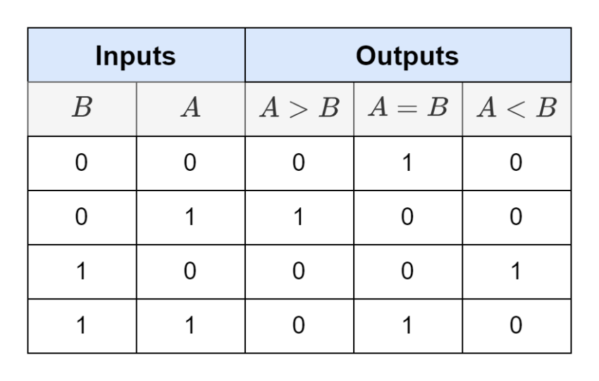
It is observable from above Truth Table that when A = B then it is not possible to distinguish between (A = B = 0) or (A = B = 1) state. Moreover, the input states and resulting output of A = B is the default or starting condition of a logic gate which is commonly available. In Digital Comparators, the Exclusive-NOR or XNOR logic gates are used to compare the bits.
Cascading of Comparators
As discussed in the previous Binary Adder article, two or more binary numbers can be added by cascading single-bit Full Adders. Similarly, a higher-order n-bit comparator can be constructed using a single-bit Digital Comparator. In this way, whole binary numbers or Binary Coded Decimal (BCD) words can be compared with each other to produce an output to know if a binary number or BCD word is equal, greater, or less than the other.
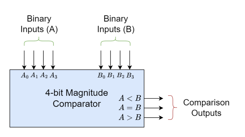
4-bit Magnitude Comparator
This can be explained by a 4-bit Magnitude Comparator whose Block Diagram is shown below. In this diagram, two 4-bit binary numbers or nibbles are compared with each other and are shown as inputs A & B. Whereas, there are only three Magnitude Comparison outputs i.e. A < B, A = B, and A > B.
In some of the commercially available Magnitude Comparators, there are additional input terminals through which comparators can be cascaded together enabling the comparison of binary numbers or words larger than 4 bits. This could possibly lead to a magnitude comparison of n-bit binary numbers. The cascading inputs are wired directly to the outputs of the previous magnitude comparator. This cascading of 4-bit magnitude comparators can achieve comparison of 8, 16, and 32-bit binary numbers. The 4-bit commercially available magnitude comparators are TTL 74LS85 and CMOS 4063.
8-bit Word Comparator
As explained above, a larger 8-bit word comparator has been shown in the figure. Here, resulting outputs are directly connected or wired to inputs of a higher-order 4-bit comparator.
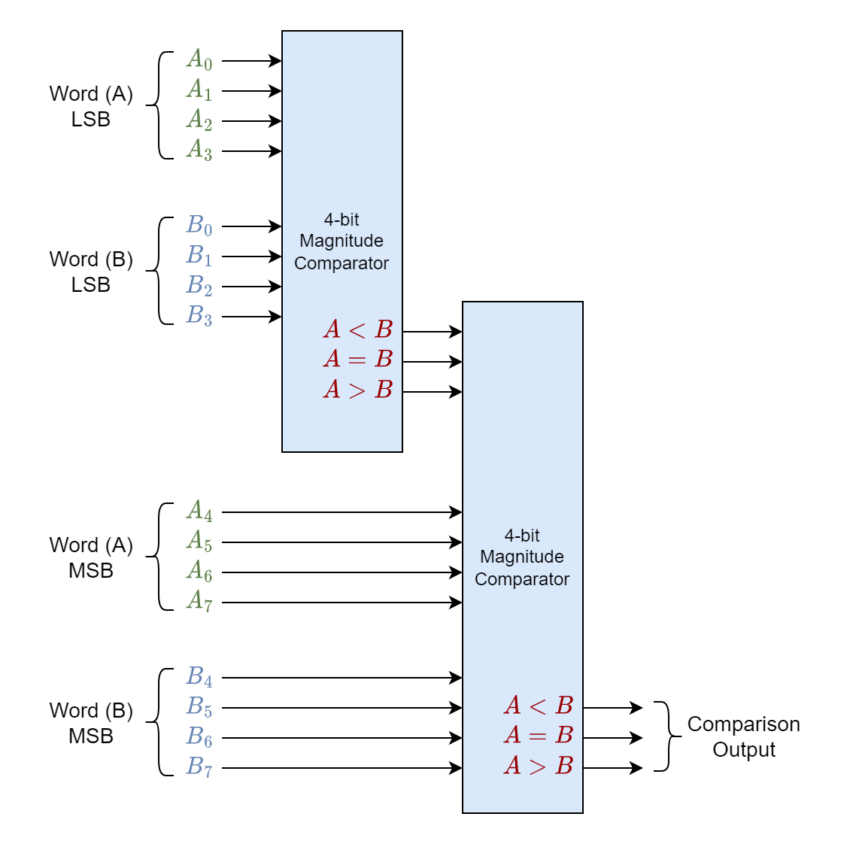
In larger word comparators, it is a practical technique adopted to first compare higher-order bit or most significant bit (MSB). If they are equal i.e. A = B then the next lower significant bits are compared and this process continues until a condition of non-equality is achieved. Otherwise, the comparison is made till the lowest significant bit (LSB) and if LSBs are found equal then both larger words are said to be equal in the comparison. In case of non-equality is found then the condition of A < B or A > B is determined.
Conclusion
- A Digital Comparator is a combinational logic circuit that compares binary values and can be constructed using Standard or Basic logic gates such as AND, OR, and NOT.
- Digital Comparators have two basic types namely Identity Comparators and Magnitude Comparators.
- Identity Comparators compare the identicality of both inputs i.e. they have the same or different states and produce resulting logic at their only output. The output is set to HIGH when both inputs are at the same state i.e. either A = B = 0 or A = B = 1.
- Magnitude Comparators compare the magnitude of both inputs and have three outputs for each possible result. The possible results of the comparison are A = B, A < B, or A > B. However, it is not possible to distinguish between equality states of A = B = 1 or A = B = 1.
- The single-bit Digital Comparators can be cascaded together to construct an n-bit Digital Comparator. The 4-bit comparators come with an additional input to allow cascading by connecting the output of the previous comparator. The commercially available 4-bit comparators are TTL 74LS85 and CMOS 4063.
- Digital Comparators are used in Arithmetic Logic Units and Analog to Digital Comparators in various functions.
Please follow and like us:
Subscribe
Login
0 Comments


