

Diode Clipping Circuits
- Muhammad Shahid
- m_shahid@live.co.uk
- 9 min
- 5.936 Views
- 0 Comments
- 2 Likes

Diode Clipping Circuits
The diode clipper is an electronic circuit consisting of a diode(s) that clips or cuts off an input signal. The output of the clipping circuit depends on the diode orientation and input signal. Such a circuit is termed, Diode Clipper. The clipped-off signal produced at the output becomes flat when a certain voltage limit has reached and due to this it is also termed as Diode Limiter.
The half-wave rectifier is an example of a diode clipping circuit because when the diode is forward biased any voltage below zero is clipped off and, similarly, when the diode is reverse biased any voltage above zero is clipped off. It is eminent from this that the most common use of clipping circuits is in voltage protection and wave-shaping circuits. Especially, equipment requiring voltage to not exceed certain voltage levels such as from overvoltages, and spikes, etc. The conventional diodes, Zener diodes, and Schottky diodes can be used to alter the input signal.
Commonly, the conventional diodes and Schottky diodes are used in signal modifications and Zener diodes in voltage protection circuits.
Working Principle
It is known from previous articles that a conventional diode can be put to operate in forward or reverse bias conditions. In forward biasing, after a certain voltage drop (0.7V for Silicon & 0.3V for Germanium) the current starts flowing and the voltage drop across the diode remains constant (0.7V or 0.3V). Whereas, in reverse biasing, the diode does not conduct and the input signal is reflected across the diode unaltered. In simple words, for an ideal diode, it becomes short-circuited when forward biased and open-circuited when reverse-biased.
The input signal can have any form or shape that may be unidirectional or bidirectional depending on the circuit application. The sinusoidal signal, which is the most commonly used alternating (bidirectional) signal, is used to explain the diode clipping.
Positive Diode Clipping
The positive diode clipping circuit clips only the positive half-cycle of the input sinusoidal signal.
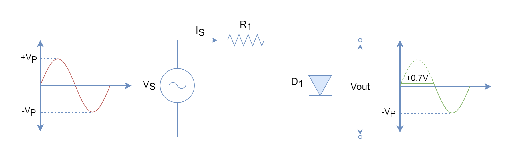
In the above figure, initially, the diode is not conducting (open) until the input voltage reaches around 0.7V during the positive half-cycle. Once, the diode starts conducting only a forward voltage drop appears across the diode irrespective of the input voltage magnitude. The positive half-cycle of the output wave depicts this with a flattened shape. During the negative half-cycle, the diode remains reverse-biased (open) and the whole input signal appears across the diode. Such a circuit only clip-off the input signal during the positive cycles i.e. any voltage above +0.7V will be clipped.
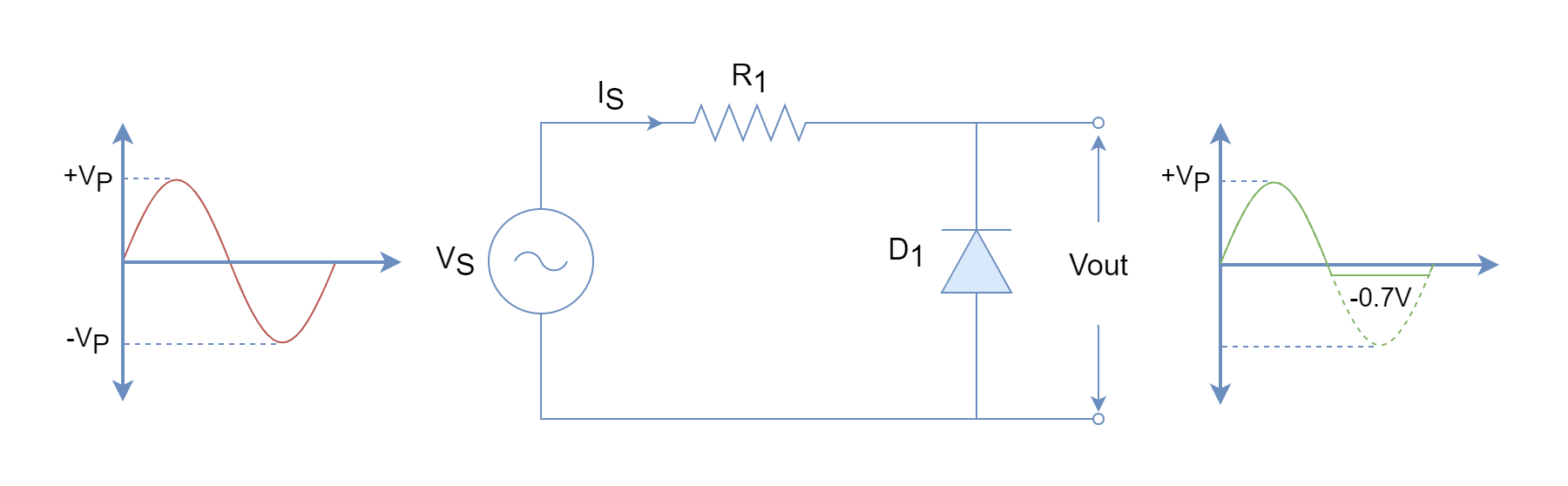
Negative Diode Clipping
In contrary to the positive diode clipping circuit, the following clipping circuit limits the voltage during the negative cycles only. The working principle is the same as described for the positive diode clipping circuit except the diode biasing is opposite. The negative clipping circuit limits negative voltage to -0.7V and any value less than this will be clipped off.
Positive & Negative Cycle Clipper
The combination of both positive and negative clipping circuits is a clipping circuit that limits voltage in both cycles. The diodes are placed in a reverse parallel arrangement and one of them conducts whilst the other remains open. During the positive half-cycle, the diode D1 conducts and D2 remains open. The reverse operation takes place during the negative cycle. The output waveform is limited to +0.7V during positive half-cycles and to -0.7V during negative half-cycles.
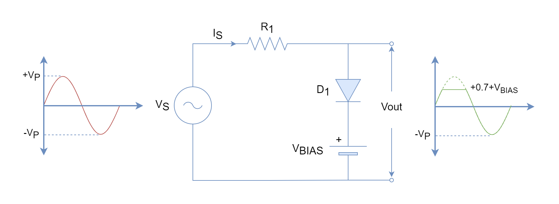
Biased Diode Clipping Circuits
The voltage limitation produced by diode-only clipping circuits is limited to forward voltage drops. In order to increase limitation, a biasing voltage is used in series with the diode to increase the level of voltage where it starts conducting. In diode only positive cycle clippers, the cathode of the diode is at zero potential and a voltage of +0.7V at the anode is required to forward bias it. However, with the addition of biasing voltage such as an EMF battery in series with the diode, the cathode potential increases to VBIAS and now for forward biasing +0.7+VBIAS is required.
Positive Bias Diode Clipper
In the following figure, a positive bias diode clipper circuit is shown. This circuit limits any voltage above +0.7+VBIAS.
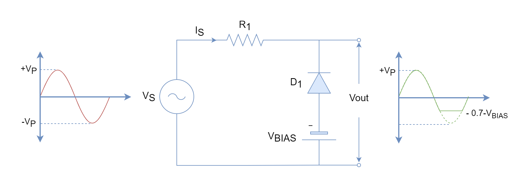
Negative Bias Diode Clipper
Similar to the positive bias diode clipper circuit, a biasing voltage in series with diode is added but in reverse polarity. The biasing aids the reverse biasing of the diode and an increased voltage is required to forward bias diode compared to the unbiased diode. Such a circuit limits any voltage below -0.7-VBIAS.
Positive & Negative Cycle Bias Clipper
In order to clip both positive and negative cycles, the positive and negative bias diodes are combined. The bias voltage for each branch can be the same or different depending on the requirements or application of the clipping circuit. Moreover, a variable voltage clipper can be made by using a variable voltage source.
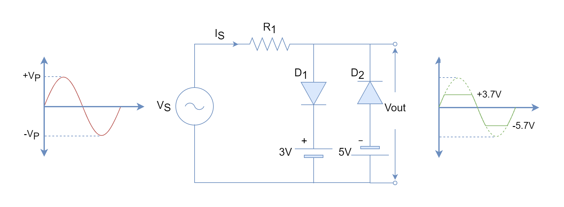
In the above figure, different biasing voltages are used to illustrate the working during positive and negative cycles. The clipping occurs at +0.7+3=3.7V and -0.7-5=-5.7V for positive and negative cycles, respectively.
The output waveform of a very low amplitude signal is clipped to a large extent leading to the square waveform. Similarly, a high amplitude signal is clipped to a small extent, and at out a square wave is produced. The application of diode circuits is to eliminate noise, fluctuation, and spikes from the input signal.
Zener Diode Clipper
A suitable clipper is one that can be designed to limit voltage accurately and with minimum components. The bias diode clipper requires biasing voltage which increases the effort and cost of the circuit. The requirement of biasing voltage can be avoided by using Zener diodes in clipping circuits. As described in the Zener Diode article, the Zener diode acts like a normal diode (0.7V forward voltage drop) when forward biased but in the reverse direction, it starts conducting above Zener voltage (VZ). The reverse current increases rapidly whilst the voltage across the Zener diode remains pretty constant. The rapid increase of Zener current requires a suitable series resistance to protect it from getting damaged.
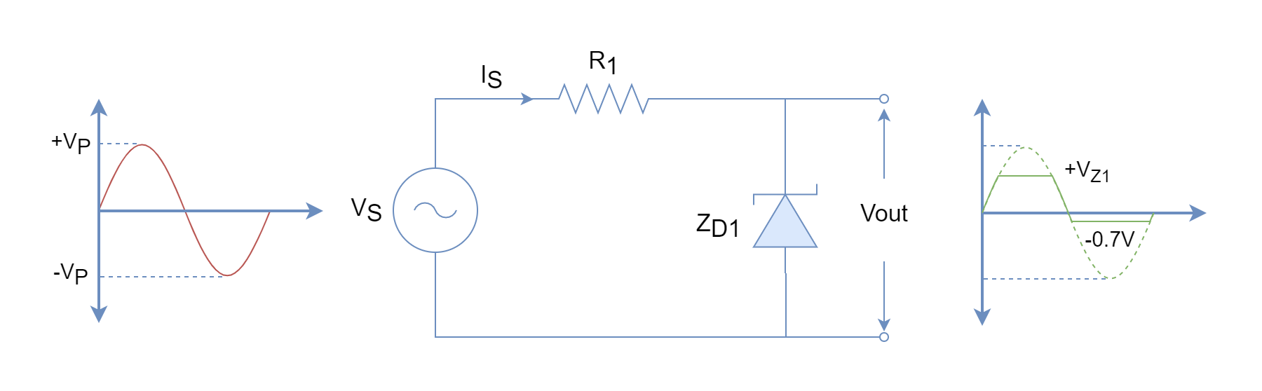
In the following diagram, a Zener diode is used to clip both cycles. However, the negative cycle clipping is somewhat limited to the forward voltage drop. The Zener diode conducts below this forward voltage drop during negative cycles and above Zener voltage (VZ) during positive cycles.
In the following figure, a full-wave clipper based on two Zener diodes is shown. In this circuit, both cycles get limited to Zener voltages (VZ) of their respective Zener diodes. Simply, the ZD1 limits positive cycles, and ZD2 limits negative cycles to VZ1 and VZ2, respectively.

The Zener diodes are available in a wide range having different Zener voltage levels and as such can be used in clipping circuits to obtain desired voltage limitations. The Zener diode-based clippers are mostly used in voltage protection circuits.
Conclusion
- The clipping circuit limits or flattens the voltage at a certain level.
- The clipping/shaping of the output waveform depends on the input signal and the circuit itself.
- The clipping can be obtained for both cycles by the inclusion of two diodes.
- The different clipping voltage levels can be obtained by using biasing voltages in series with the diodes.
- The Zener diode can also be used in clipping circuits by operating it in the Zener breakdown region.
- The Zener diode-based clipping circuit eliminates the use of diode biasing voltage.
Please follow and like us:
Subscribe
Login
0 Comments


