

Exclusive NOR Gate
- Muhammad Shahid
- m_shahid@live.co.uk
- 1.344 Views
- 0 Comments
- 0 Likes

Exclusive-NOR Gate
The Exclusive-NOR logic is the complement (reverse) form of the Exclusive-OR logic. It is the serial combination of Exclusive-OR and the NOT gates. The Exclusive-NOR gate gives an output given by the expression “Both A & B, not A or B”. It means that the output of the Exclusive-NOR gate is “HIGH” when both inputs “A” and “B” are at the same logic level i.e. both “HIGH” or “LOW”. In the case of, either “A” or “B” that is “01” or “10” the output of the Exclusive-NOR gate will be “LOW”. The Exclusive-NOR gate outputs logic “HIGH” only when both of its inputs are equal and, therefore, it is sometimes referred to as “Equivalence Gate”.
The Exclusive-NOR is also referred to by writing only Ex-NOR or XNOR. The Ex-NOR is a very useful logic and is mostly used in circuits involving arithmetic operations such as Parity Checkers, Adders and Subtractors, etc.
Similar to the Ex-OR gate, the construction of Ex-NOR logic is complex compared to other logic gates and is constructed using basic logic gates. Similarly, the Ex-NOR gate is also commercially available as a separate logic gate. Because of its construction from multiple basic logic gates, it is also called a “hybrid” logic gate. The truth table of the logic NOR gate is somewhat similar to the Ex-NOR gate in that its output remains at logic level “HIGH” and goes to “LOW” when any of its inputs goes “HIGH”. However, the Ex-NOR gate’s output goes “HIGH” again when both of its inputs go to logic level “HIGH”.
The Boolean algebraic equation of an Ex-NOR logic is given below:
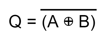
The equivalent circuit of an Exclusive-NOR gate is:

Logic Ex-NOR Gate Symbol & Truth Tables
The representation of an Ex-NOR logic by a symbol is shown in the following figure.

The symbol of the Ex-NOR logic is similar to the Ex-OR logic except for an “Inversion Bubble” which is added at the output to denote the “NOT” function.
The truth table of a two-input Ex-NOR logic is shown below:
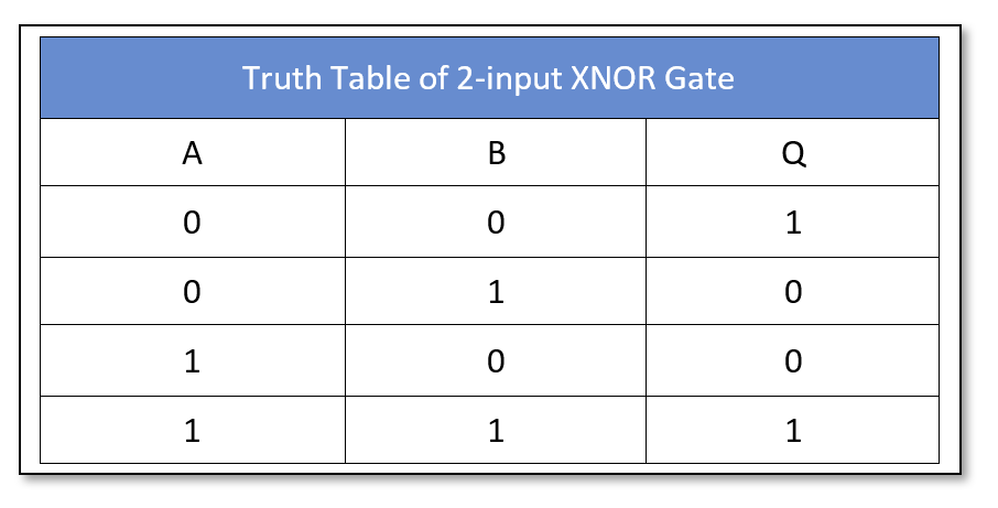
It is clear from the truth table that when inputs are at the same levels i.e. either “00” or “11” state then the Ex-NOR logic output is “HIGH” and in case the inputs are at the different levels then output is “LOW”. In other words, the expression is “A” AND “B”, Same!
The truth table of a three-input Ex-NOR logic is as follow and can be expanded to include any number of inputs:
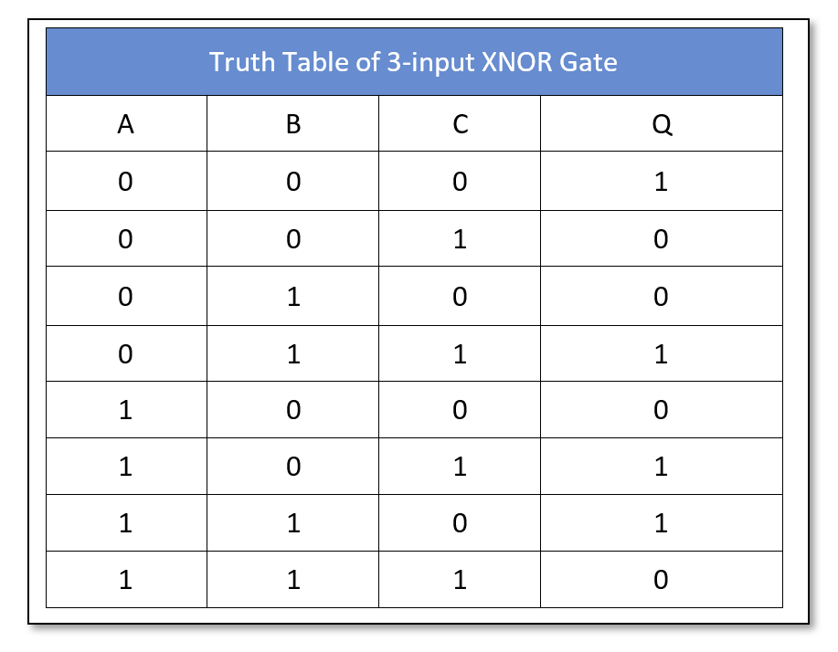
As discussed in the previous article, the Ex-OR logic is an odd function and gives a logic “HIGH” output when there is an odd number of inputs having logic “HIGH” or “1”. Whereas, the Ex-NOR logic is an even function which is eminent from the truth tables given above. The Ex-NOR logic gives a “HIGH” output when inputs with the logic “HIGH” are in even numbers except for the case when all of the inputs are “OFF” or at logic “LOW”. This characteristic makes the Ex-NOR an even gate.
The symbol and expression of a 3-input Ex-NOR logic are given below:

Ex-NOR (XNOR) Logic Circuit
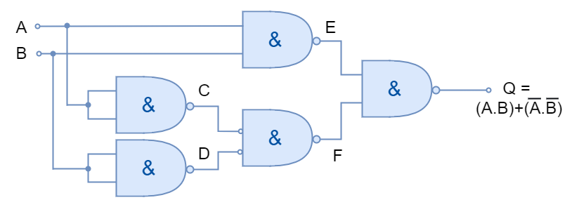
Using the logic expression of a two-input Ex-NOR logic, an equivalent circuit can be constructed which is shown in the following figure.
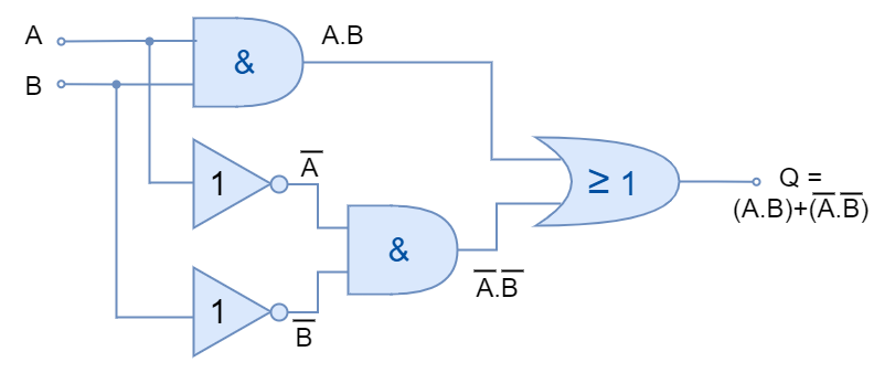
The above equivalent Ex-NOR logic comprises AND, OR, and NOT logic. However, it is not a good practice to include multiple logics for the construction of logic gates and a better Ex-NOR circuit can be constructed using only NAND logic gates.
The construction of the Ex-NOR gate using NAND gates only is shown below:
The Exclusive-NOR logic gates are helpful in performing arithmetic operations and computations. They are also used in data error detection circuits as Parity Bit Checkers.
Commercially Available E-NOR (XNOR) Gates
The XNOR logic gates are available in both TTL and CMOS logic families. The most commonly used XNOR logic packages are:
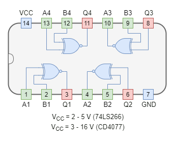
CMOS based XNOR Gate IC Package
- CD4077 Quad 2-input
TTL based XNOR Gate IC Package
- 74LS266 Quad 2-input
Example of XNOR Logic
In the following figure, an XNOR gate is used to drive a 12V relay to switch on the lamp using NI Multisim. The XNOR gate turns on the relay when all of the inputs are connected to VCC/ Ground. The relay thus turns on the lamp through an external circuit of 12V. When inputs are at different levels, XNOR logic goes “OFF” turning the relay and lamp to “OFF” state.
Conclusion
- The output of the Ex-NOR logic is “HIGH” when both of the inputs have the “SAME” logic states.
- The Ex-NOR gate outputs logic “LOW” when inputs have different logic states.
- The Ex-NOR gate checks for the equality of the inputs and as such also known as Equivalence Gate.
- It is an Even Parity Checker as it outputs a “HIGH” signal when there is an even number of signals at the input having logic “HIGH”.
- It is mostly used in arithmetic, computational and error-detection circuits.
- The Ex-NOR logic gates are commercially available in both TTL and CMOS packages.
- An external circuit can be controlled by Ex-NOR logic with the use of a magnetic relay.
Please follow and like us:
Subscribe
Login
0 Comments


