

Input and Output Impedances of Amplifiers
- Boris Poupet
- bpoupet@hotmail.fr
- 12 min
- 35.538 Views
- 1 Comments
- 1 Likes

Introduction
In a very simplified point of view, an amplifier consists of a “box” that realizes an amplification function between an input signal and an output signal. The way that the input enters the system and the output leaves it is very important and affects the general behavior of an amplifier. In more technical terms, the flow of current of both the input and output is controlled by the input and output impedance of the amplifier.
This tutorial clarifies the notions of input and output amplifiers impedances by explaining the previously mentioned concept of “box”. The second section highlights the several reasons of importance of choosing appropriate values for these parameters. Finally, some methods are exposed to set the amplifier’s impedances, therefore to greatly affect the circuit behavior.
Definition of the input and output impedances
First of all, it is important to realize for the understanding of this tutorial that the input and output impedances are a concept and do not represent any physical resistor that can be removed or changed. Indeed, they represent a value in Ohms (Ω) that takes into consideration the design of the amplifiers (the arrangement of the components around the transistor) and to what and how they are connected (source, other amplifiers or transducers). We will detail later on these different connection arrangements.
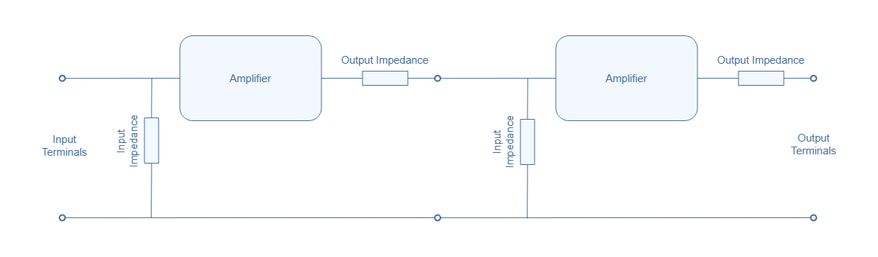
The input impedance is connected across the input terminals of the amplifier while the output impedance is connected in series with the amplifier. A representation of this configuration is shown in Figure 1 below :
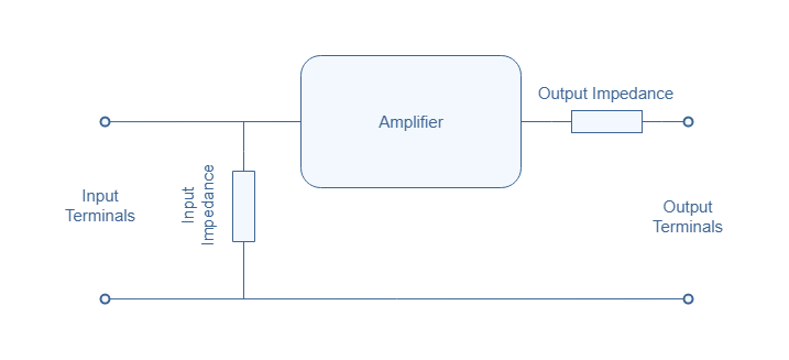
If we consider the input voltage and current to be Vin and Iin and the output voltage and current to be Vout and Iout, the simplest definitions of the impedances Zin and Zout are given by :
- Zin=Vin/Iin
- Zout=Vout/Iout
Generally, an input impedance is high and an output impedance is low. Ideal amplifiers have an infinite input impedance and a zero value for the output impedance.
Importance of the Impedances
If there is something to really keep in mind about why input and output impedances are so important is matching. Impedance matching is a simple concept that states that the power transfer from an internal source resistance (RS) to a load (RL) is maximized when RS=RL. A simple representation is given below to define the different parameters in this context :

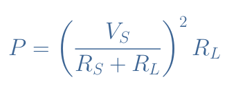
This theorem can be proved easily through some calculation steps that involves derivative calculus. The expression of the transferred power P as a function of VS, RS and RL is given in Equation 1 below :
However, maximum transferred power does not imply maximum efficiency. It is indeed a common source of error since even Joule himself misunderstood it. Efficiency relates to the percentage of power that can be transferred from the source to the load, whereas the transferred power refers to the maximal magnitude of the power that the load can develop.
The formula for the efficiency satisfies Equation 2 :
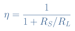
Both the transferred power and efficiency can be plotted in the same graph as a function of the ratio RL/RS :
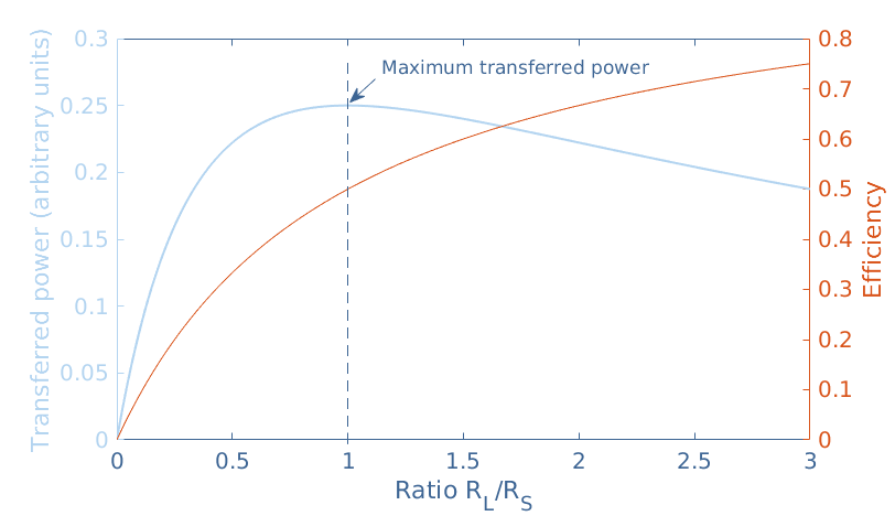
From Figure 3 we can indeed see that the transferred power is maximized when the impedances are matching, that is to say when RL/RS=1. For a perfect impedance match, the efficiency only reaches 50 %. A 100 % ideal efficiency is achieved when the ratio RL/RS tends to an infinite value, that is to say when RL→+∞ or RS→0 or both.
Without even considering this graph, it is indeed easy to understand that when RL>>RS, most of the power is transferred to the load since the voltage across a resistance is directly proportional to its value in Ohms. However, when the ratio RL/RS increases, so does the global resistance of the circuit and therefore the magnitude of the transferred power decreases.
On the other hand, if the load resistance is lower than the source resistance, most of the power is dissipated in the source, leading to a poor efficiency of the power transfer even if the global resistance decreases, which results in a higher magnitude of the power.
So should the impedances match to achieve a maximum transferred power or should RL>>RS to achieve maximal efficiency ?
Nowadays, as a general rule, high input and low output impedances are the norm, even if it does not lead to an impedance match. However, we will see in the next section that in some cases, impedance matching can be more suitable.
“Impedance conflicts” happens between an output and an input terminal. Basically, we can distinguish three scenarios of connection. The first one, is when a source is connected to an amplifier, this is what is shown in Figure 2.
The second case is when the amplifier is connected to a transducer. A transducer is the final stage of the circuit, it is the element that converts the electric signal into sound and movement for example, examples of transducers are loudspeakers and motors. The configuration of this connection is the same as presented in Figure 2 where the source would be the amplifier and the load the transducer.
The last scenario is the so called “cascade” configuration shown in Figure 4 where multiple amplifiers are connected to each other. In modern electronics, this type of architecture is very common to realize multiple operations and amplifications to the signals.
Impedance setting
In the input stage, where a power supply (source RS) is connected to an amplifier (RL), a maximum transferred power is not necessary since the amplifier can itself re amplify the signal. Usually, a signal loss of -6 dB between the source and the first amplifier (commonly known as preamplifier) is acceptable, such a loss is achieved when an impedance match is realized. Therefore, technically any ratio of output/input impedance that satisfies RL/RS>1 can be considered. Since it is never recommended to have an input impedance lower than the value of the internal source resistance, amplifier’s input resistances are high so that they can adapt to a wide variety of sources, thus to many values of source resistances..
In the case of the cascade configuration presented in Figure 4, two functioning modes can be distinguished and treated differently :
- If a voltage transfer is to be realized, the output impedance of the first amplifier should be much lower than the input impedance of the next amplifier. This maximizes, such as what we described for the input stage, the voltage drop across the input impedance of the second amplifier rather than in the output impedance of the first.
- If a power transfer is to be realized, it is more appropriate to match the impedances so that a maximal magnitude of the power can be transferred across several stages of amplifiers.
For the final stage, where a last amplifier supplies a transducer (lets say a loudspeaker), the output impedance of the amplifier must be lower than the internal loudspeaker resistance. Again for the same reasons, the power is transferred more efficiently to the transducer if the amplifier has a low output impedance. In this case, most of the power can be used by the transducer. However, the global resistance should not be too high to avoid a low power magnitude.
Setting methods
The input and output impedances values are fully given by the architecture of the amplifiers. We can list some of the architectures that are available in order to modify the input or output impedances :
- FET input stage : Field Effect Transistors such as the MOSFET can be used to connect the source to the preamplifier. Since their gate is purely voltage-driven, they do no take any current at the input and thus provide a very high input resistance.
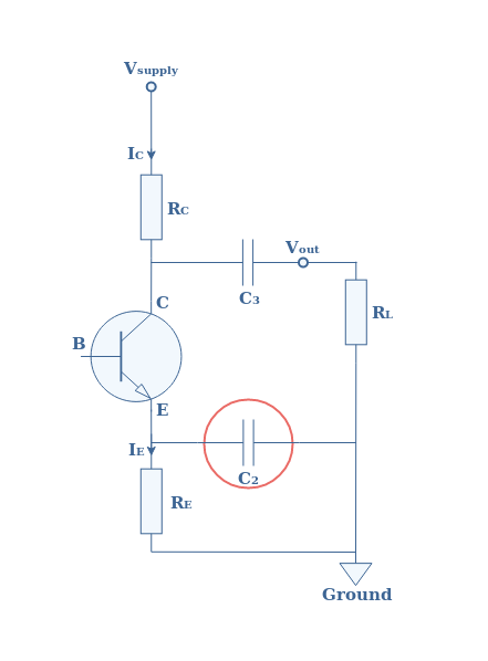
- Decoupling capacitors : In the Figure 5 , a decoupling capacitor in the output stage of a Common Emitter configuration is highlighted in the red circle. In the Common Emitter Amplifier tutorial, we have already seen that using a derivation capacitance increases the gain of the amplifier. However, it also decreases the input impedance of the structure. Adjusting the value of this capacitance can therefore modify the value of the input impedance of the amplifier.
- Emitter-follower : One of the easiest solution to obtain both high input and low output impedances is to use the emitter-follower configuration. Much more details of this configuration can be found in the tutorial about the Common Collector Amplifier.
Conclusion
This tutorial has first of all defined what exactly the input and output impedances are. We have seen that they represent the total resistances of the amplifier at the input terminals and at the biased output terminals. Since they do not represent any physical resistance they cannot be removed, but as a consequence of the amplifier architecture, their value can be adjusted.
These impedances play an important role at the interfaces of the amplifiers. They indeed dictate how the voltage or power signals are being transmitted from either a source to a preamplifier, from an amplifier to another amplifier or from an amplifier to a transducer.
Two criteria are mostly used in order to set the impedances : the transferred power or the efficiency. Generally, a high efficiency is preferred for voltage amplifiers. It can be achieved by setting the input impedance of the stage n+1 much higher than the output impedance of the stage n. With this configuration, despite the global resistance increasing, much of the power is developed at the n+1 stage input terminals rather than dissipated by heat losses in the output.
Sometimes however, it can be suitable to obtain a maximum of transferred power by realizing an impedance matching. In this case, the input and output impedances are set to be equal so that the power magnitude is maximal at the n+1 stage input terminals. This configuration is appreciated in power amplifier where a power transmission must be privileged.
Finally, we have seen that changing the input and output impedances must be done by modifying the architecture of the amplifier. A wide variety of configurations are indeed available, but some of the most important are given in a last section.
Please follow and like us:


Isn’t power equal to (V squared)/Rtotal?