

Logic OR Gate
- Muhammad Shahid
- m_shahid@live.co.uk
- 1.182 Views
- 0 Comments
- 1 Likes

Logic OR Gate
The logic OR gate gives an output of logic “HIGH” when any of its inputs goes to the “HIGH” logic level.
The logic OR gate can have multiple inputs and only one output. The logic OR gate gives an output of logic “LOW” only when all of its inputs are at logic “LOW” level and the output changes to logic “HIGH” at the instant state when any input changes from level “LOW” to “HIGH”.
Similar to logic AND gate, the logic OR gate has a Boolean logic or expression. The Boolean expression of logic OR gate is that of a Logical Addition and is expressed by the plus (+) sign between the inputs (operands). The logical OR expression with inputs A & B is given by:
A + B = Q
As in digital logic circuits, there are only two states i.e. “0” or “1”. The addition (+) of anything with “1” will always be a “1” which simply expresses a logic OR gate.
The logic OR gate gives a true output when both of the inputs are true and can be termed as “Inclusive OR gate”. The “Exclusive OR Gate” gives a false output when all of its inputs are at logic high. The “Exclusive OR Gate” will be discussed later in the article.
Resistor – Transistor OR Gate
The logic OR gate can be constructed using the Resistor – Transistor Logic (RTL) circuit. The logic OR gate construction requires two Resistor – Transistor Logic (RTL) connected in a parallel configuration as shown in the below figure.
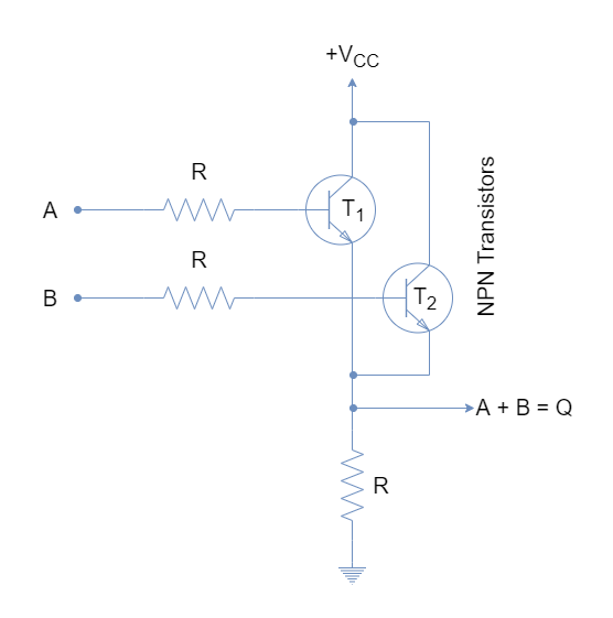
The inputs are connected to the base of transistors and output is taken from a common emitter/ across the resistor. The transistors are biased such that they operate in saturated “ON” & “OFF” states. A logic “HIGH” or +5V at any of the inputs will shift the relevant transistor from saturated “OFF” to “ON” state and an output “HIGH” will appear across the resistor (R).
Logic OR Gate Symbol & Truth Tables
The representation of an OR logic by a symbol is shown in the following figure. Its symbol denotes the addition/ OR logic operation.

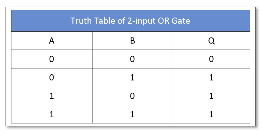
The truth table of a two-input OR logic gate is shown below:
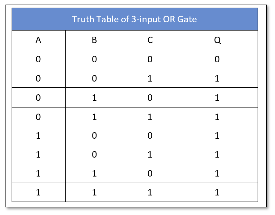
 Similarly, the truth table of a three-input OR logic gate is as follow:
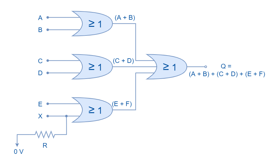
The Boolean expression can be extended to include multiple inputs to obtain OR logic operation. However, commercially available OR logic circuits have up to four inputs but the number of inputs can be further extended by cascading the OR logic circuits. In the following figure, three two-input logic OR gates and one three-input logic OR gate are cascaded to construct a six-inputs (2 x 3 = 6) OR logic circuit.
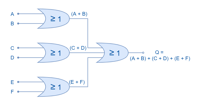
The Boolean expression for this cascaded circuit can be written as:
Q = (A + B) + (C + D) + (E + F)
Odd Number of Inputs
The logic OR circuit having an odd number of inputs can be constructed by connecting the unused input to logic “LOW”. This will ensure that another input(s) of the logic OR gate is truly reflected at the output. It is explained in the following diagram where unused input is pulled down using a pull-down resistor.
Commercially Available OR Gates
The logic OR gates are available in both TTL and CMOS logic families. The most commonly used OR logic packages are:
CMOS based OR Gate IC Package
- CD4071 Quad 2-input
- CD4075 Triple 3-input
- CD4072 Dual 4-inputs
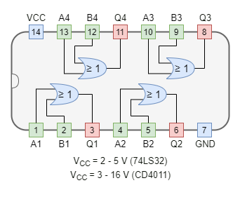
TTL based OR Gate IC Package
- 74LS32 Quad 2-input
Example of OR Logic
In the following figure, an OR gate is used to drive a 12V relay to switch on the lamp using NI Multisim. The OR gate (74LS32) energizes the relay when any of its inputs is connected to VCC. The relay thus turns on the lamp through an external circuit of 12V. When all of the inputs are connected to ground OR logic goes “OFF”, turning the relay and lamp to “OFF” state.
Conclusion
- The output of the logic OR is “LOW” when all of the inputs are in logic “LOW” states.
- Any of the inputs in the logic “HIGH” state will drive OR logic to the “HIGH” state.
- The logic OR gates can be constructed using Resistor-Transistor Logic (RTL) but are seldom used because of the propagation delay and power consumption.
- The Transistor-Transistor Logic (TTL) and Complementary Metal-Oxide Semiconductor (CMOS) are commonly used for digital circuits construction.
- The logic OR gates commercially available have up to four logic OR gate inputs. However, inputs can be extended by using cascaded OR logic gates.
- The logic OR circuit having an odd number of inputs can be constructed by using a pull-down resistor on the unused pin.
- An external circuit can be controlled by an OR logic with the use of a magnetic relay.
Please follow and like us:
Subscribe
Login
0 Comments


