

Sinusoidal Waveforms
- Boris Poupet
- bpoupet@hotmail.fr
- 10 min
- 9.500 Views
- 0 Comments
- 0 Likes

Introduction
Within a period of 10 years at the end of the 19th century, many technological achievements allowed to extend the use of alternating current and overcome the limitations of direct current for the distribution of electricity to the public.
In 1882, the transformer is invented in France which eases the distribution of the alternating current as we will mention in the first section. Only six years later, Tesla created the first prototype of the synchronous machine which as we detail in the main core of this tutorial, generates a particular form of alternating current from a primary form of energy.
This particular alternating current can be described by a mathematical function and is commonly known as a sine or sinusoidal waveform. In this tutorial, we will refer to several previous articles to regroup information and give more details about the sinusoidal waveform.
First of all, a short presentation will define the important parameters of a sine function and why it is so important in electronics.
In a second section, we investigate their generation process with alternators which includes an understanding of electromagnetic phenomena. We focus on the architecture of the rotor and stator which are the two most important parts involved in electricity generation.
Presentation
Sine waveforms are found in many domains of maths and physics and they can be mechanical or electrical for example. They describe a periodic and smooth oscillation of a certain parameter (current, voltage, movement …etc).
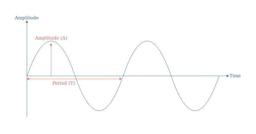
The electrical sine waveform is described mathematically by the sine function y(t) and the general formula is given below :
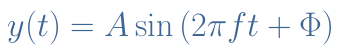
The parameter A is the amplitude which unit is in Amps (A) or Volts (V), f is the frequency of oscillation in Hertz (Hz) or the angular velocity ω in radians/second (rad/s) and Φ is the instant phase of the signal in degrees (°) or radians (rad). The oscillation speed can also be given by the period T=1/f which represents the time duration of a cycle.
We also remind the reader that Equation 1 can be transformed into its complex equivalent for simplification and compaction purposes, such as detailed in the tutorial about Complex Numbers.
The conversion between radians to degrees can easily be done knowing that 2π rad=360°. Moreover, the frequency and angular velocity are linked by the identity ω=2πf.
An illustration of these parameters is given in Figure 1 that compares two different sine functions.
In order to know if the phase is different from zero, we can look at the variation of the sine around the origin of time. A sine wave with no instant phase should have an amplitude of 0 at t=0 and increase right after, which is the case of the blue sine function y2(t).
Before talking about the production of such signals, it is worth mentioning why they are so interesting and why they are used in so many applications.
First of all, as we will see in the next section, sine signals can be naturally produced with generators in power plants. Moreover, as already detailed in the AC Waveform tutorial, they are the building blocks of any other period signals such as squares, ramps … Finally, the entire distribution network is based on the use of sine power waveform because their current and voltage amplitudes can easily be adjusted to specific needs with the help of transformers, the transmission power losses are as well decreased.
Generation
The reader is encouraged to refer to our previous articles about AC Waveform and AC Inductance in order to get a preview of what this section will detail in the following.
The generation of an electrical sine signal is done by a synchronous electric motor also known as alternator. The goal of such a device is to transform mechanical energy (rotation) into electricity.
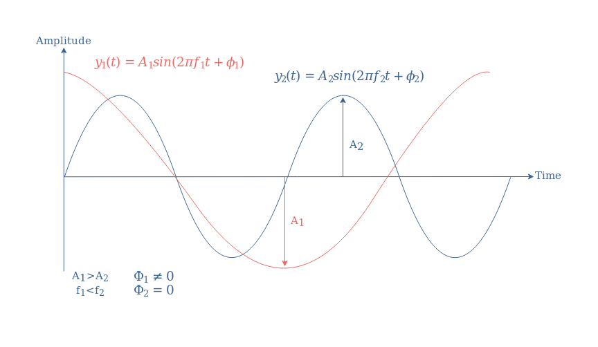
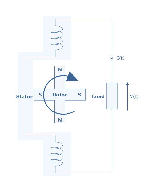
The following Figure 2 presents the schematic architecture and the functioning of a single pole-pair alternator :
The alternator consists of two parts : a stator and a rotor. As the name refers to, the stator is a stationary coil in which the AC electricity is induced and harvested. The rotor is a rotational magnet that generates a magnetic field inside the stator.
The rotation of the rotor is maintained by a primary form of energy : combustion of coal or nuclear material, wind, movement of water in a dam etc … It can be a permanent magnet in which the magnetic field is constant or an electromagnet in which the magnetic field can be tuned depending on the electricity supplied to it. Often, the second option is chosen because a variable amplitude of the magnetic field allow to change the amplitude of the output electrical signal.
The stator is where the induced electric signal is generated thanks to the induction phenomenon. The electric signal produced is naturally a sine waveform because of the circular symmetry of the configuration.
Indeed, according to the induction law, the electric signal e (either the current or voltage) is proportional to the variation of the magnetic flux ΦB within the stator: e=-dΦB /dt. If AS states for the area of the stator coil, we can define a surface vector given by AS=AS.n with n being the unit normal vector to the same surface as shown in Figure 3 :
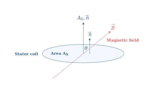
The magnetic flux is simply given by a vectorial product of the field B and the area vector of the stator coil AS :
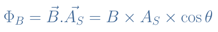
If we set the angle θ to be at 0° when the axis of the rotor and stator are aligned, we can understand that ΦB=Φmax×cosθ with Φmax=B×AS, the variations of the flux is, therefore, also a sine waveform since the derivative of a cosine is a sine and the angle θ is a function of time. Finally, we can say that the electric output will be as well a sine waveform.
Rotor pole-pairs
An important relation between the frequency of the electric sine output (f) can be given and the rotation speed of the rotor (in RPM) : RPM=60×f. In order to obtain a 50 Hz signal, which is the distribution norm in Europe, the rotor must rotate at 3000 RPM. This high speed can be achieved in a nuclear power plant but in dams, for example, the rotation is much slower.
To maintain a frequency of 50 Hz, a solution consists of increasing the number of pairs of poles of the rotor such as illustrated in Figure 4. With this configuration, a faster variation of the magnetic flux is achieved for the same rotation speed.
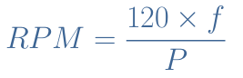
For this example, a 50 Hz output can be observed with a rotation speed of 1500 RPM instead of 3000 RPM. In the general case, if P states the number of pole-pairs, the relation between the rotation speed and output frequency is given by the Equation 3 :
Stator pole-pairs
In the previous illustrations, the stator consists of only 1 pair of the pole which gives a single-phase current. For high-power applications, however, such as high-voltage distribution, a 3-phase current is more suited since it presents fewer power losses and a more constant average power.
The architecture of such a stator is presented in the Figure 5 below :
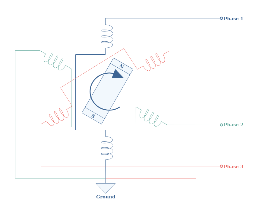
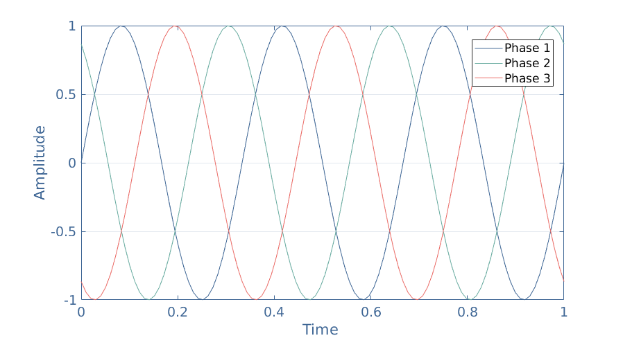
Each phase is separated 120° from the rotation center of the rotor and one pole of each phase in grounded. The total output is, therefore, a combination of 3 sine waves phase-shifted 120° such as presented in the Figure 6 :
Most of the modern alternators consist of a 3 pole-pair stator which allows the production of 3-phase sine waves and provides better efficiency. Moreover, a multi pair-pole rotor can be combined in this configuration in order to obtain the required frequency even if the mechanical rotation is slower than 3000 RPM.
Conclusion
Sine waveform plays a major role in many physics domains and especially in electronics since they are present in our daily life, supplying households for more than a century, worldwide.
In the first section of this tutorial, we mathematically described what a sine wave consists thanks to the sine function and explained the amplitude, frequency and phase parameters. We also briefly explain the importance of such signals.
The main core of this article refers to the production of sine signals through the use of alternators. They consist of a rotational part (the rotor) that creates a variable magnetic field in a static coil (the stator) surrounding it. According to the electromagnetic law of induction, an electric sine wave is produced in the stator.
We have pinpointed that the number of pole-pairs of both the stator and rotor can be modified in order to maintain a 50 Hz output with a slower rotation of the rotor or to achieve a 3-phase signal for high-power applications.
Please follow and like us:
Subscribe
Login
0 Comments


