

Star-Delta Transformation
- Boris Poupet
- bpoupet@hotmail.fr
- 13 min
- 3.341 Views
- 0 Comments
- 0 Likes

Introduction
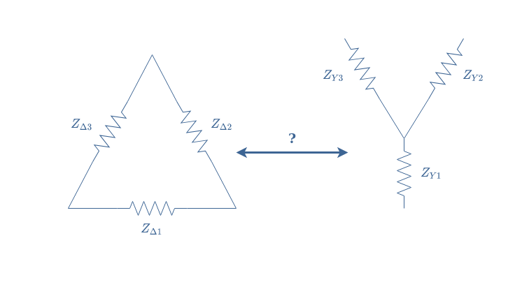
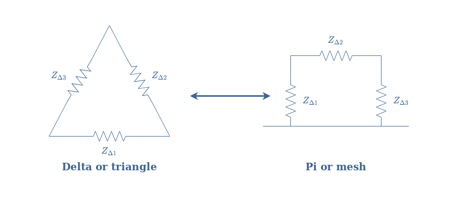
This article will focus on an electronic transformation of circuits known as star-delta transform or Y-Δ transform, which names come from the shape of the circuits involved and presented in Figure 1. The goal of this article is to understand how to transform a Y configuration to a Δ configuration and reciprocally, in which context this transformation is useful and why.
First of all, we present the domain in which such topologies are usually found: in three-phase power circuits. We will briefly describe its functioning and advantages in comparison to the mono-phase circuits.
In the second section, we give more details about the Y and Δ configurations. We will see that such configurations are found both at the source and reception stages of three-phase circuits.
The third section focuses on the Y to Δ and Δ to Y transformations. We will illustrate the theory with some examples and explain how this transformation can simplify the study of three-phase circuits.
Presentation
We highlight in this section the difference between single-phase and poly-phase electric configurations. The reader can refer to the Sine Waveform tutorial where we have already presented some key information.
Single-phase configuration
A single-phase configuration refers to the fact that the production, distribution, and reception of the power is realized with only one AC signal.
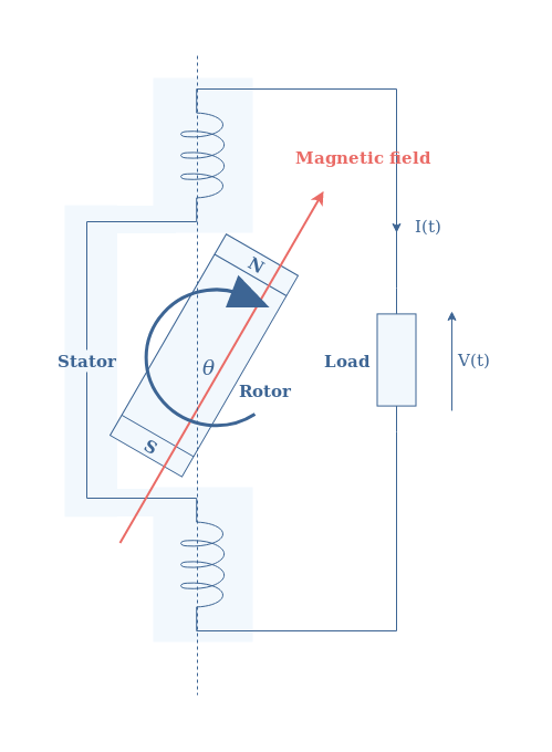
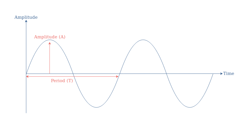
As we can see in Figure 2, only one pole-pair is present in the stator of the alternator, which generates only one AC signal or phase of the following shape:
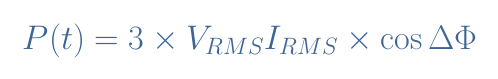
In a single-phase configuration, as explained in the AC Power tutorial, the power transmitted to the load has a constant and a time-varying term:

VRMS and IRMS are respectively the voltage and current root mean square values. ΔΦ represents the phase difference between the voltage and current signals and ω their common angular pulsation.
The major problem of single-phase power configurations is that the alternating power term can cause the destruction of the output alternator by causing oscillations in the drive shaft.
For this reason, it is necessary for high-power applications to rely on a poly-phase generation system.
Poly-phase configuration
In a poly-phase configuration, many AC signals (voltage or current) are generated by a source, transported, and received by a load. The number of phases depends on the number of pole-pair coils that can be found in the stator of the alternator. Worldwide, the choice of three phases has been adopted, such as illustrated in Figure 3 below:
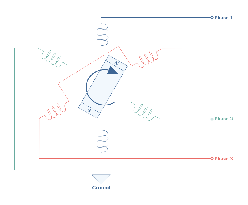
In such a configuration, each pole-pair is separated from a 120° angle, which also results in a time phase-shift of the same value:
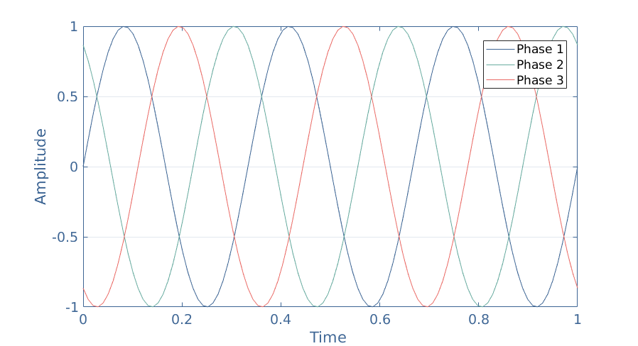
When N phases are phase-shifted equally of 360°/N, we say that speak of balanced three-phase system.
Getting the expression of the instantaneous power for a three-phase configuration is not complex but it involves a lot of repetitive and long steps. It can be shown however that the final expression of the instantaneous power is no longer depending on the time parameter, as shown in Equation 2:
The pulsating term of power encountered in Equation 1 for single-phase configurations is in fact canceled for any n-phase configuration with n≥2.
Poly-phase systems present other advantages such as a better power transmitted/mass of cables ratio used.
Three-phase connections
In this section, we give more details about the networks presented in Figure 1.
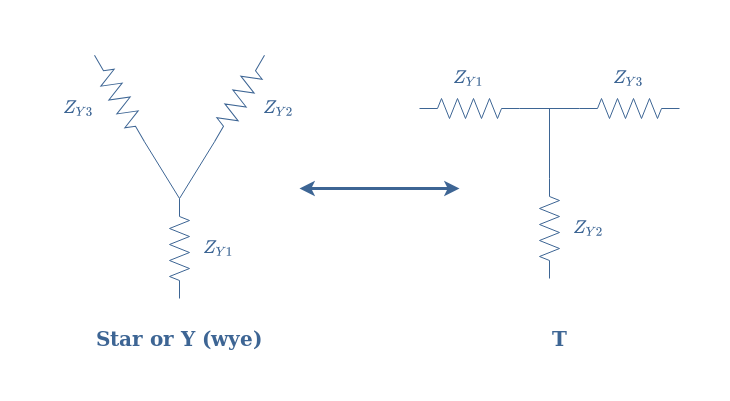
Y configuration
It is worth to mention that we can find many names in order to describe this topology. The star, Y (or wye), and T network all refer indeed to the same topology, depending on how the circuit is drawn:
If we actually focus on how the coils are interconnected in Figure 3, we can see that they are all connected to a grounding node. In fact, the connection used as an example in Figure 3 is a Y configuration.
A complete Y three-phase system consists of sources, lines, and receptors (impedances) such as presented in the following Figure 5:
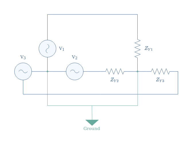
Due to the presence of ground, in a star configuration, every coil of the motor sees a reduced voltage (divided by √3).
Let’s consider a Y three-phase system in which ZY1=ZY2=ZY3=25 Ω and the sources are supplied with a 3×120 V AC signal, we suppose that cos(φ)=1. Since the impedances are equal, the voltage in each resistor is given by 120/√3=69 V. The same remark is valid for the current, their value is equal and given by 69/25=2.8 A.
The active power, according to Equation 2, is finally given by P=3×69×2.8=580 W.
Δ configuration
Such as for the Y configuration, many names refer to this topology: Delta (or Δ), triangle, Pi (or Π), or mesh.
A complete Δ three-phase system consists of sources, lines, and receptors (impedances) such as presented in the following Figure 6:
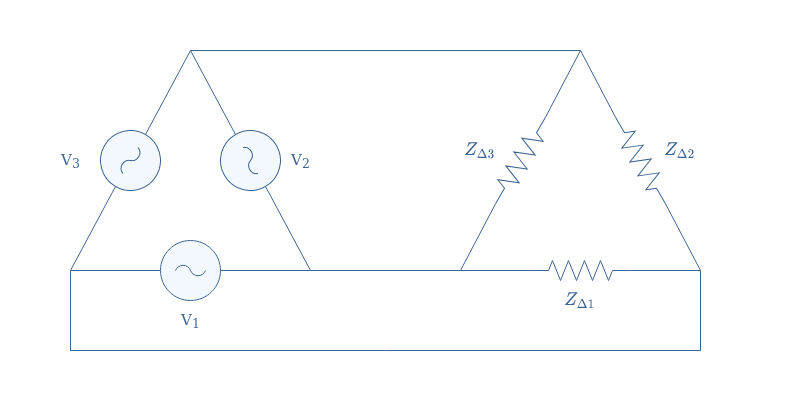
We can note that no grounding is present in a Δ configuration, for this reason, every coil of the motor sees directly the voltage applied.
We reconsider the same example than given previously with ZΔ1=ZΔ2=ZΔ3=25 Ω and supply of 3×120 V. In Δ configuration there is no ground, for this reason, the voltage across each resistor is equal to the supply of 120 V. The RMS intensity in each line is given by 120/25=4.8 A.
The active power is therefore given by P=3×120×4.8=1730 W.
For the same impedances and supply, the Δ configuration is more powerful than a Y configuration by a factor 3.
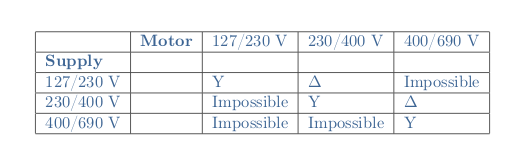
The choice of a Y or Δ configuration depends on the value of the supplied voltage and the nominal voltage of the motor used. The voltages are written for example 230/400 V which signifies that 230 V is the voltage between phases and 400 V between a phase and the ground.
The Y configuration is chosen when the supply and nominal voltages are equal, the Δ when the phase-to-ground supply is equal to the phase-to-phase of the motor. Moreover, some associations are impossible and given in the following table:
Y-Δ and Δ-Y transformations
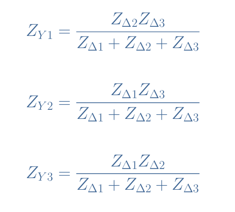
These transformations allow us to convert a Y to a Δ configuration and reciprocally. We can also refer to these conversions as Kennelly’s theorem. The impedances present in the circuits will be labeled exactly such as formally presented in Figure 1.
Y-Δ
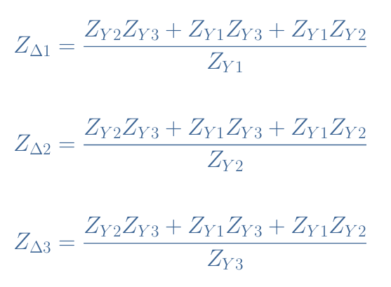
The transformations Y-Δ and Δ-Y simply consist of a series of formulas to follow. For the Y-Δ conversion, we proceed such as:
Δ-Y
For the reciprocal formulas used for the Δ-Y transformation, we proceed such as:
Application
Let’s consider the following circuit of Figure 7 for which we want to find the equivalent resistance:
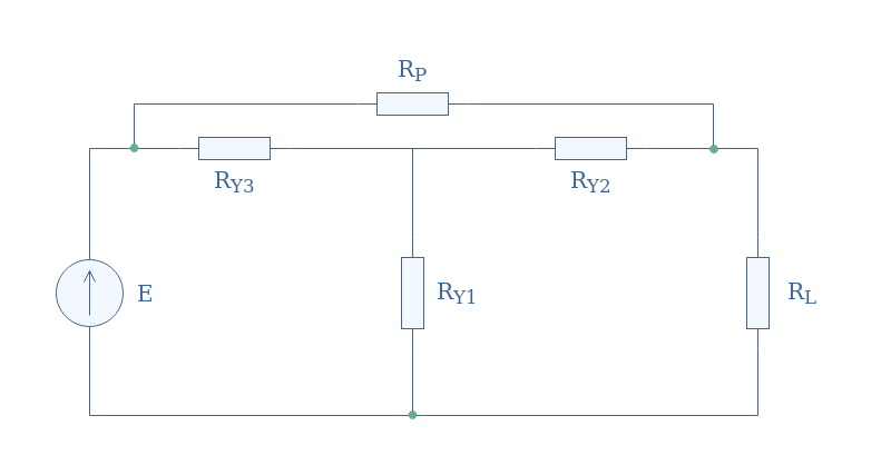
We recognize in between the green nodes a Y configuration formed by the resistor RY1, RY2, and RY3. In order to find the equivalent resistance of this circuit, we transform the Y configuration by a Δ structure formed by the resistor RΔ1, RΔ2, and RΔ3 which formulas are given by Equations 3.
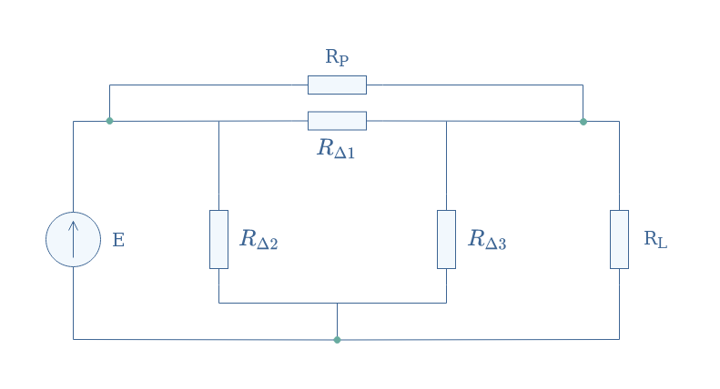
Finally, the equivalent resistance Req is given by associating the remaining resistors in parallel: Req=[(RP//RΔ1)+(RL//RΔ3)//RΔ2].
Conclusion
This tutorial has focused on two special connections that can mostly be found in three-phase circuits, known as Star, Y, or T configuration and Δ, Triangle, or Π configuration. The goal was to understand in which context, how, and why these two configurations can reciprocally be converted from one to another.
Three-phase circuits are first of all discussed, we have seen that they are more suitable for high-power applications since a problematic pulsating term that can damage an output engine is present in single-phase circuits and eliminated with poly-phase generation.
After presenting the context, we give more details concerning the Y and Δ configurations. These configurations are actually found in poly-phase systems both at the generation and reception stages. We highlight the fact that a Δ configuration gives more active power than a Y connection. Moreover, the choice of the connection depends both on the available supply of the network and the required supply for the engine to be driven.
The Y to Δ and Δ to Y transformations formulas are presented in the last section. An application shows a typical example in which a Y to Δ transformation is used in order to simplify the process to retrieve an equivalent resistance of a given circuit.
Please follow and like us:
Subscribe
Login
0 Comments


