

The Demultiplexer
- Muhammad Shahid
- m_shahid@live.co.uk
- 764 Views
- 0 Comments
- 0 Likes

The Demultiplexer
The Demultiplexer or DEMUX is a combinational logic circuit that connects one input line to one of the several output lines, one at a time. Like a Multiplexer, the Demultiplexer contains no memory, storage, or feedback. Being a combinational logic circuit, its output is solely dependent on the information present on its input lines. Demultiplexing refers to the reverse of the Multiplexing process. As discussed in the previous article, the Multiplexer combines several input lines into a single channel or output line for sending information or data which may be either analog or digital. The reverse of Multiplexing is to combine several output lines into a single channel connecting to an input line. For a multiplexer, there is more than one (1) input and only ONE output. Whereas, for a Demultiplexer, there is only ONE input and several output lines.
The input line is routed or switched to output lines one at a time by the application of a control line(s). Similar to the multiplexers, the demultiplexers are like mechanical rotary switches which select one of the output lines or channels to be switched to the common input.
The Demultiplexers are also classified into Analogue and Digital categories. The Multiplexers and Demultiplexers are used in pairs and should match their construction, signal-handling capabilities, etc.
The selection of output lines in demultiplexers is controlled using separate input lines which are referred to as “Select Lines”. The logical combination of these Select Lines helps in selecting one of the output lines. For example, a logical “LOW” at the select line means to select Output Line-0, and a logical “HIGH” to select Output Line-1. The data output lines are normally in even numbers and are given by 2n. Whereas, the “n” corresponds to the number of control inputs required for the selection of data output lines.
Demultiplexer Symbol
In the following figure, a Demultiplexer symbol has been shown. It is the simplest one-to-two (1-to-2) Demultiplexer.
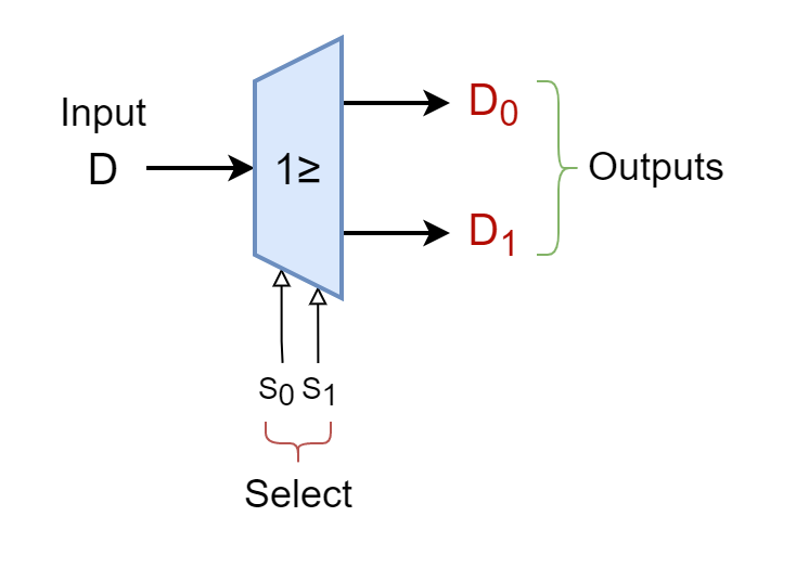
1-to-2 Demultiplexer
In the following figure, a 1-to-2 Demultiplexer has been shown along with its truth table.
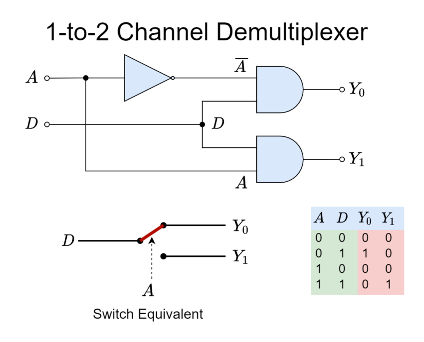
The above 1-to-2 Demultiplexer is constructed using basic logic gates. The data input line is D and the output lines are Y0, & Y1. The Select or Control Line is indicated by input A. From the logic diagram and given Truth Table, it is obvious that when Select Input “A” is “LOW” or “0” then Output Line “Y0” gets selected as an output. The signals present on input pass through the logic circuit and appear at output “Y0”. Whilst, the Output Line “Y1” gets blocked when Select Line “A” is set to “LOW”. The output selection phenomena get reversed when Select Line “A” is set to “HIGH” or “1” i.e. the Output Line “Y1” connects with the input “D” and Data Output “Y0” gets blocked.
By simply setting the Select Line “A” to “LOW” or “HIGH” logic, the input line can be switched to the outputs depending on the logic level of “A”. The given circuit is acting as a Single-Pole-Double-Through (SPDT) switch. As discussed above, with only one (1) Select line i.e. n=1, the input line can be switched to a total of two (2n = 21 = 2) output lines. The described circuit is the simplest form of a Demultiplexer which is a 1-to-2 Demultiplexer.
The 1-to-2 Demultiplexer is the simplest or basic form of a Demultiplexer which has only one (1) input and two (2) outputs. In order to increase the number of outputs of a Demultiplexer, a 1-to-2 Demultiplexer can be used as a basic building block for the construction of higher-output Demultiplexers. As mentioned above, the number of outputs of a Demultiplexer will be in even numbers so the next stage after two (2) output-Demultiplexer is a four (4) output-Demultiplexer. For a four (4) output Demultiplexer, a total of two (n = 2) Select Lines are required.
1-to-4 Demultiplexer
In the following figure, a 1-to-4 Demultiplexer has been shown along with its Truth Table.
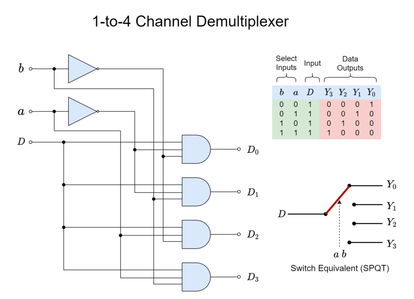
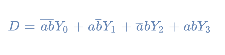
In the above 1-to-4 Demultiplexer, the Output Lines are Y0, Y1, Y2, and Y3 and the Select Lines are “a”, and “b”. The Boolean expression of the above-given 1-to-4 Demultiplexer is:
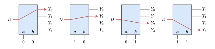
The 1-to-4 Demultiplexer circuit acts as a Single-Pole-Quad-Through (SPQT) switch. At any instant, only one of the four outputs will be connected to the input “D” whilst others remain blocked depending on the logic conditions of Select Lines “a” and “b”. For example, in order to connect the Data Input “D” to the Output Line “Y2”, the logic states required are “A=0” and “B=1”. Likewise, other Data Output selections can be made by setting the logic states of Select Lines, accordingly. The selection of Output Lines against the logic states of Select Lines is shown in the following figure.
The output lines of a Demultiplexer can be further increased to 8, 16, … etc. by increasing the select lines to 3, 4, … etc., respectively.
Adjustable Amplifier Gain Application
In the Multiplexer article, an adjustable gain amplifier was constructed using a multiplexer in the feedback. The same can be achieved by using a Demultiplexer but instead of using it in the feedback, it is placed at the input of the amplifier circuit. In the following figure, an adjustable inverting operational amplifier has been shown with multiple input paths depending on the amplification required.
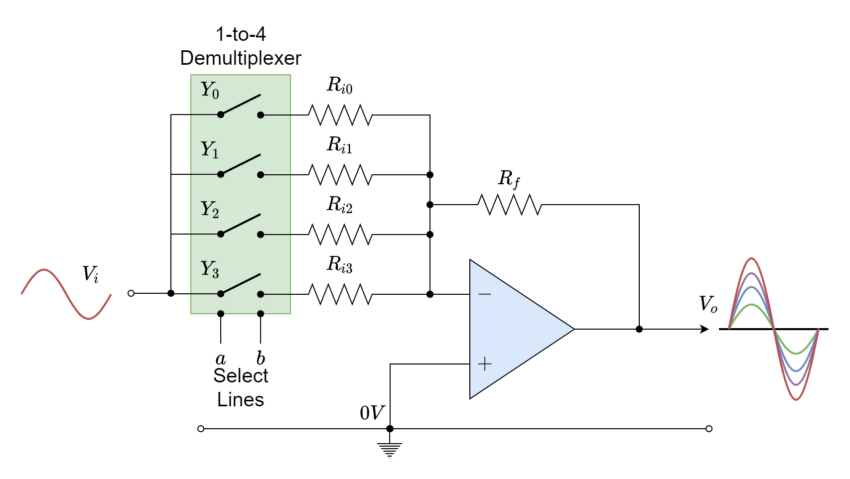
The placement of the Demultiplexer at the input is obvious as it essentially converts a single input to multiple paths. Each path has been set to present a different input resistance which ultimately sets the gain of the amplifier. The gain of the amplifier is mainly dependent on input and feedback resistances. However, in the above configuration, the gain is adjustable using only input resistance as the feedback resistance is fixed. The gain of the input signal (audio) will be set as per Select Lines which are setting the input resistance of the op-amp.
The Demultiplexers are used in the reception of single-input data to distribute over multiple channels, buses, or transmission lines such as in Digital Systems, LAN or Ethernet Switches, etc.
The Demultiplexers are commonly available in commercial I.C. packages such as in TTL: 74LS15138 (Single 1-to-8), and 74LS139 (Dual 1-to-4) or in CMOS: CD4514 (Single 1-16) Demultiplexers, etc. The number of inputs of a Demultiplexer can be increased by cascading the aforementioned TTL or CMOS devices. Most of the commercial I.C. packages come with Enable pin which enables or disables the operation of Demultiplexing.
Conclusion
- A Demultiplexer is a combinational logic circuit with the ability to switch a single input line to one of several output lines.
- Being a combinational logic circuit, the Demultiplexer’s output is dependent on the state of inputs only and, as such, uses no memory, storage, or a feedback path.
- The selection of individual output lines is made through the “Select” or “Control” line(s). The number of “Select” or “Control” lines yields the number of Output Lines that can be controlled i.e. 2n. Where “n” represents the number of “Select” or “Control” lines. For example, in a Demultiplexer with two (n=2) Select Lines, a total of four (2n = 22 = 4) Output Lines can be switched to the common Data Input Line. Because of this, the number of Output Lines is in even numbers.
- The digital Demultiplexers are used for the reception of serial data over a single line to distribute over multiple channels, buses, etc. The analog demultiplexers are commonly used in the pre-amplification of audio, and video signals.
- The Demultiplexers are commercially available in form of I.C. packages such as 74LS15138 (Single 1-to-8), 74LS139 (Dual 1-to-4), and CD4514, etc.
Please follow and like us:
Subscribe
Login
0 Comments


")