
The Multiplexer
- Muhammad Shahid
- m_shahid@live.co.uk
- 503 Views
- 0 Comments
- 0 Likes

The Multiplexer
The Multiplexer or MUX is a combinational logic circuit that connects one of the several input lines to a single output line. It is a combinational logic circuit and, as such, it is memoryless, without storage, and feedback involved. The multiplexer’s output is solely dependent on the information present on its input lines. In general, the term Multiplexing describes the operation to combine several input lines into a single channel or output line for sending information or data which may be either analog or digital. The input lines are routed or switched to the output one at a time by the application of a control line(s). The multiplexers are like mechanical rotary switches which select one of the lines or channels to be switched to the output. However, in contrast to the rotary switches, the switching of Multiplexers is rapid and yields a high data rate.
Depending on the construction, the Multiplexers can be categorized into Analogue or Digital Multiplexers. The digital multiplexers are constructed using high-speed digital logic gates which are used in Ethernet or LAN etc. Whereas, the analog multiplexers are constructed from Metal Oxide Field Effect Transistors (MOSFET), transistors, relays, etc. which are used for switching voltage or current input signals to the output line.
A Basic Multiplexing Switch
In the following figure, a basic rotary one-way switch is shown.
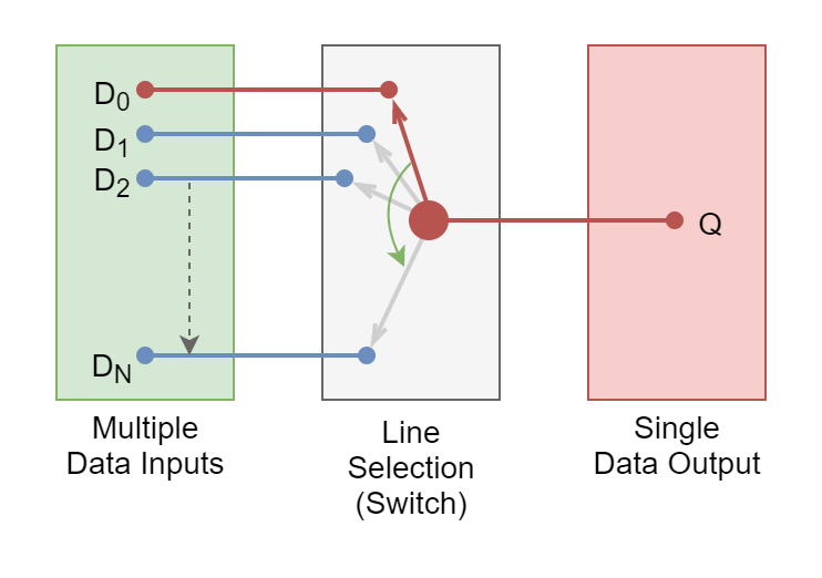
The rotary switch is a mechanical device with different layers connecting to input lines. The selection of one of the layers or input lines is controlled using a shaft attached to these layers. The mechanism of the rotary switch is such that the rotation of the shaft slides the output line between the layers and ultimately connects one of the inputs to the single output depending on the position of the rotary shaft.
The Multiplexers are also known as “Data Selectors” in digital electronics as they “select” data input lines. On the other hand, they are sometimes referred to as “Channel” selectors in analog electronics as they select one of the voltages or current channels. They are constructed using analog switches such as transistors or MOSFETs as opposed to rotary switches described earlier.
The purpose of the multiplexer is to reduce the number of data or signal lines. For example, when one data line or bus is available and two or more different signals are required to be transmitted using it then multiplexing is applied to achieve this. As explained earlier in the rotary switch operation, input selection or switching is made using the rotary shaft. Likewise, the selection of input lines in multiplexers is controlled using separate input lines which are referred to as “Select Lines”. The logical combination of these Select Lines helps in selecting one of the input lines. For example, a logical “LOW” at the select line means to select Input Line-0, and a logical “HIGH” to select Input Line-1. The data input lines are normally in even numbers and are given by 2n. Whereas, the “n” corresponds to the number of control inputs required for the selection of data input lines.
Multiplexer Symbol
In the following figure, a Multiplexer symbol has been shown. It is the simplest two-line-to-one (2-to-1) Multiplexer.
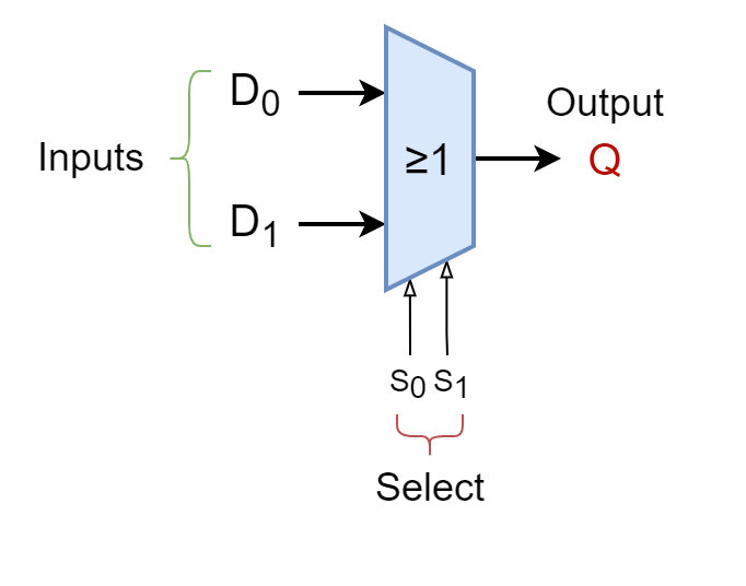
2-to-1 Multiplexer
In the following figure, a 2-to-1 Multiplexer has been shown along with its truth table.
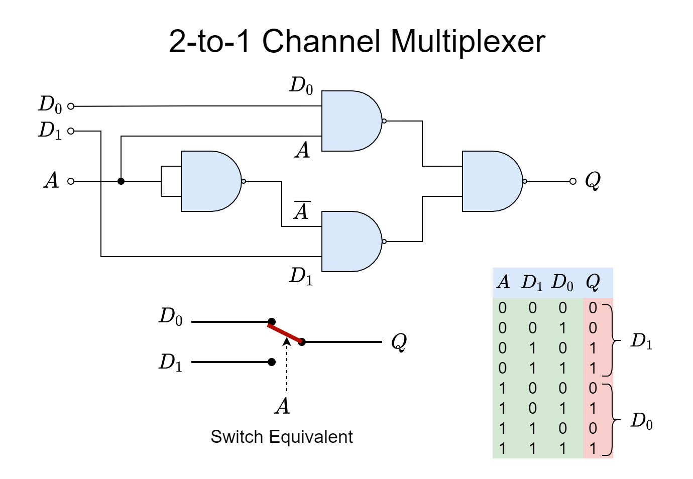
The above 2-to-1 Multiplexer is constructed using only NAND gates. The data input lines are D0, & D1 and Q is the single output. The Select or Control Line is indicated by input A. From the NAND logic and given Truth Table, it is obvious that when Select Input “A” is “LOW” or “0” then Data Line “D1” gets selected as output “Q”. The signals present on “D1” passes through the logic circuit and appear at output “Q”. Whilst, the Data Line “D0” gets blocked when Select Line “A” is set to “LOW”. The input selection phenomena get reversed when Select Line “A” is set to “HIGH” or “1” i.e. the Data Line “D0” connects with the output “Q” and Data Input “D1” gets blocked.
By simply setting the Select Line “A” to “LOW” or “HIGH” logic, the input lines can be switched to the output depending on the logic level of “A”. The given circuit is acting as a Single-Pole-Double-Through (SPDT) switch. As discussed above, with only one (1) Select line i.e. n=1, a total of two (2n = 21 = 2) input lines can be switched. The described circuit is the simplest form of a Multiplexer which is a 2-to-1 Multiplexer. The above logic circuit in Boolean expression can be described as follow:
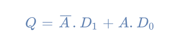
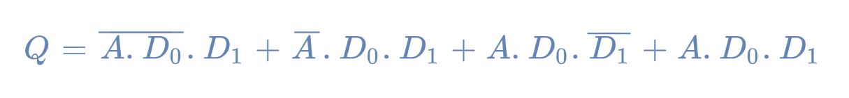 The above equation upon simplification yields:
The 2-to-1 Multiplexer is the simplest or basic form of a Multiplexer which has only two (2) inputs and one (1) output. In order to increase the number of inputs of a Multiplexer, the same procedure can be followed and a 2-to-1 Multiplexer can be used as a basic building block for the construction of higher input Multiplexers. As mentioned above, the number of inputs of a Multiplexer will be in even numbers so the next stage after two (2) input-Multiplexer is a four (4) input-Multiplexer. For a four (4) input Multiplexer, a total of two (n = 2) Select Lines are required.
4-to-1 Multiplexer
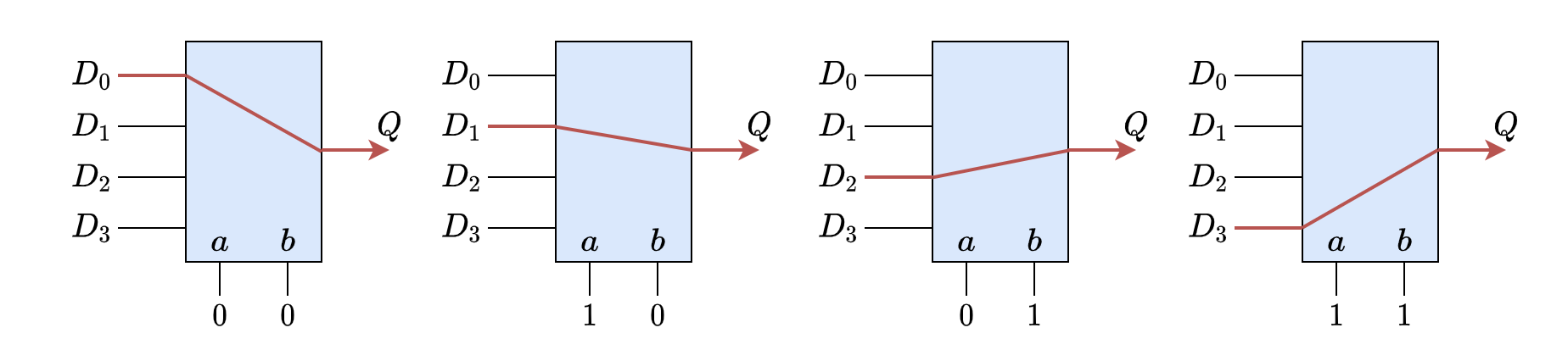
In the following figure, a 4-to-1 Multiplexer has been shown along with its Truth Table.
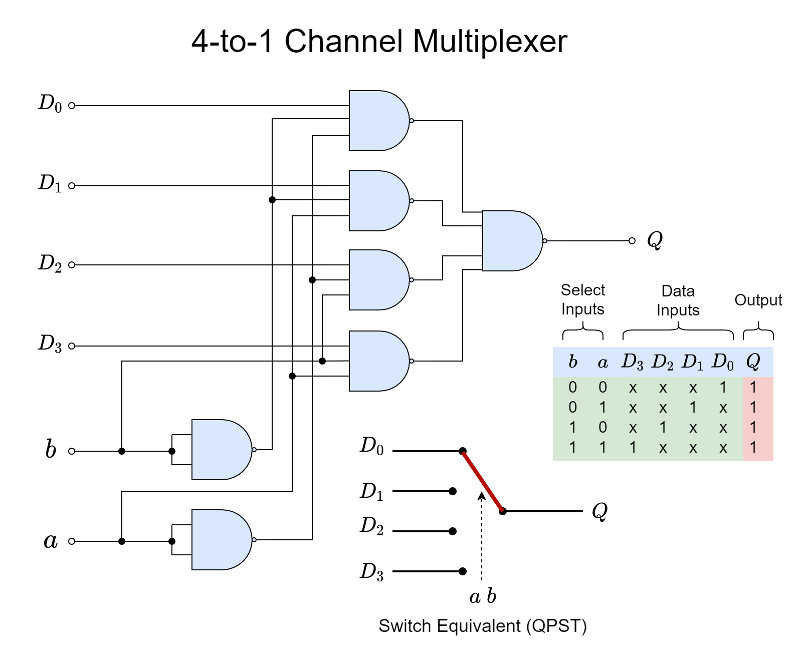
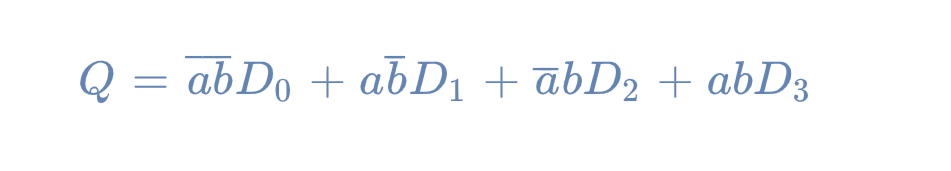
In the above 4-to-1 Multiplexer, the Data Lines are D0, D1, D2, and D3 and the Select Lines are “a”, and “b”. The Boolean expression of the above given 4-to-1 Multiplexer is:
 The 4-to-1 Multiplexer circuit acts as a Quad-Pole-Single-Through (QPST) switch. At any instant, only one of the four inputs will be connected to the output “Q” whilst others remain blocked depending on the logic conditions of Select Lines “A” and “B”. For example, in order to connect the Data Input “D2” to the output, the logic states required are “A=0” and “B=1”. Likewise, other Data Input selections can be made by setting the logic states of Select Lines, accordingly. The selection of Data Lines against the logic states of Select Lines is shown in the following figure.
The input lines of a Multiplexer can be further increased to 8, 16, … etc. by increasing the select lines to 3, 4, … etc., respectively.
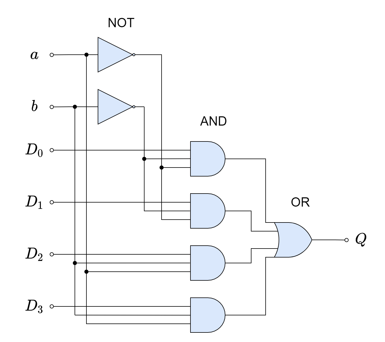
The above Multiplexer circuits are constructed by using only NAND logic gates. The 4-to-1 Multiplexer would require seven (7) individual basic logic gates i.e. AND, OR, and NOT for the construction of the same as shown below.
The multiplexers which are shown above, 2-to-1 and 4-to-1, have only single output. The 2-to-1 or 4-to-1 Multiplexer can be combined with its duplicate to produce a two (2) output multiplexer circuit. For example, a logic circuit can be constructed using two individual 2-to-1 Multiplexers with their Select Lines combined. Such a Multiplexing circuit, would consist of two 2-to-1 Multiplexers but with only two Select Lines (combined). Each 2-to-1 Multiplexer will be a mirror image of the other and the logic circuit would produce two outputs as shown below. It is referred to as a 4-to-2 Multiplexer.
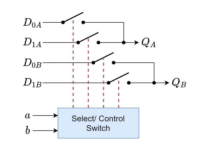
The larger arrangements can be produced by adding the single channel multiplexer(s). Such multi-output multiplexers are commonly used for switching the audio signals in pre-amplifiers or mixers etc.
Adjustable Amplifier Gain Application
Besides the transmission of data over single-line from Multi-inputs, the Multiplexers are also used in the pre-amplification of multi-channel analog audio signals. In the following, an inverting operational amplifier has been shown with multiple feedback paths depending on the audio channels.
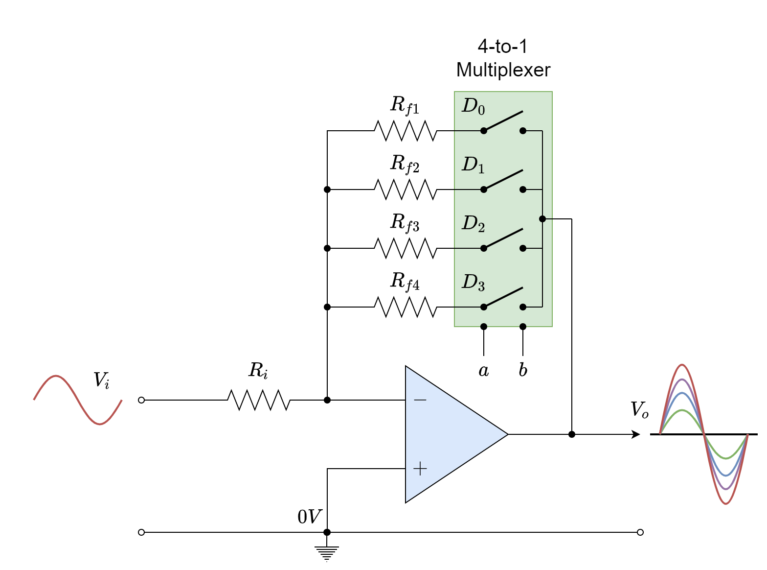
As it is known that the Amplification or Gain of an inverting operational amplifier is dependent on the Feedback Resistance (Rf) and, as such, a multi-gain amplifier circuit can be achieved by selecting one of the multi-feedback resistance paths one at a time. In order to achieve this, a multiplexer can be used in the feedback paths as shown in the above following figure. Depending on the Select Lines, the feedback path will be selected and the gain of the op-amp, accordingly.
The gain of the input audio signal will be set as per Select Lines which are ultimately setting the feedback resistance of the op-amp.
The Multiplexers are also known as “Data Selectors” because of their capability to select individual data lines. In digital communication, they are used in the transmission of multi-input data over a single transmission line such as in LAN or Ethernet Switches.
The Multiplexers are commonly available in commercial I.C. packages such as in TTL: 74LS1518 (Single 8-to-1), 74LS53 (Dual 4-to-1) Multiplexers, etc. The number of inputs of a multiplexer can be increased by cascading the aforementioned TTL devices. Most of the commercial I.C. packages come with inverted “NOT” output in addition to the non-inverted output. Hence, a complemented output of the input data signal is also made available at the terminal.
Conclusion
- A Multiplexer is a combinational logic circuit with the ability to switch one of the several input lines to a single common output line.
- Being a combinational logic circuit, the Multiplexer’s output is dependent on the state of inputs only and, as such, uses no memory, storage, and a feedback path.
- The simplest form of a Multiplexer is a Rotary Switch which connects one of the several inputs to the single output depending on the shaft position.
- The selection of individual input lines is made through the “Select” or “Control” line(s). The number of “Select” or “Control” lines yields the number of Input Lines that can be controlled i.e. 2n. Where “n” represents the number of “Select” or “Control” lines. For example, in a multiplexer with two (n=2) Select Lines, a total of four (2n = 22 = 4) Input Lines can be controlled. Because of this, the number of Input Lines is in even numbers.
- Digital multiplexers are used for the transmission of serial data over a single line, selection of data bus, etc. Analog multiplexers are commonly used in the pre-amplification or mixing of audio, and video signals.
- The Multiplexers are commercially available in form of I.C. packages such as 74LS1518 (Single 8-to-1), and 74LS53 (Dual 4-to-1).
Please follow and like us:
Subscribe
Login
0 Comments


")
