All Activity
- Past hour
-
 Esm Famil joined the community
 - Today
-
seems to be dead here!
-
I just wondered if the max voltage out will be low because of the 10v zenner next to q3?.
-
 An Tong The joined the community
 -
 FET-MX8MP-SMARC System on Module(SoM) is developed based on the NXP i.MX 8M Plus processor, focusing on machine learning, vision, advanced multimedia, and highly reliable industrial automation. It caters to applications such as smart cities, industrial IoT, smart healthcare, and intelligent transportation. With powerful quad-core or dual-core ARM® Cortex®-A53 reaching up to 1.6GHz and an NPU achieving 2.3 TOPS, it integrates ISP and dual camera inputs for efficient advanced vision systems. Multimedia features include video encoding (including H.265) and decoding, 3D/2D graphics acceleration, and various audio and voice functions. Real-time control is achieved through Cortex-M7, with a powerful control network using CAN-FD and dual Gigabit Ethernet, supporting Time-Sensitive Networking (TSN). It features high-speed communication interfaces such as 2 x USB 3.0, 1x PCIe 3.0, and 1x SDIO 3.0, meeting the requirements of 5G networks, high-definition video, dual-band WiFi, high-speed industrial Ethernet, and other applications. Explore more about this SoM now! https://www.forlinx.net/product/imx8mpq-smarc-system-on-module-153.html
- Yesterday
-
 jetufhj joined the community
 -
 Reinaldo Escorcio joined the community
 -
 Thanks for sharing it, I will surely check it.
 -
 JamesMVictoria reacted to a post in a topic:
Integrating DHT11 with Beetle ESP32 C3 and Home Assistant
JamesMVictoria reacted to a post in a topic:
Integrating DHT11 with Beetle ESP32 C3 and Home Assistant
-
 thejemas joined the community
 - Last week
-
 sh Basit joined the community
 -
 Kavin Mithran GK joined the community
 -
 Carlos Duran Ramirez joined the community
 -
 This is a rather complicated process, you will have to look for it.
 -
 ahmed elkhateeb joined the community
 -
 CrabiPlay joined the community
 -

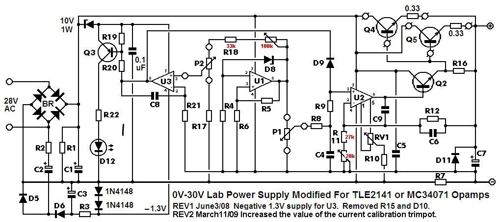
Guitar Level To RCA Line Level Preamp
Paul Bober replied to Paul Bober's topic in Electronic Projects Design/Ideas
My apologies to the Electronics-Lab Community. I should have sent this version of my schematic for the Guitar Level To RCA Line Level Preamp. In this version of the schematic, a 5K feedback resistor is used on A2. This schematic also looks more symmetrical.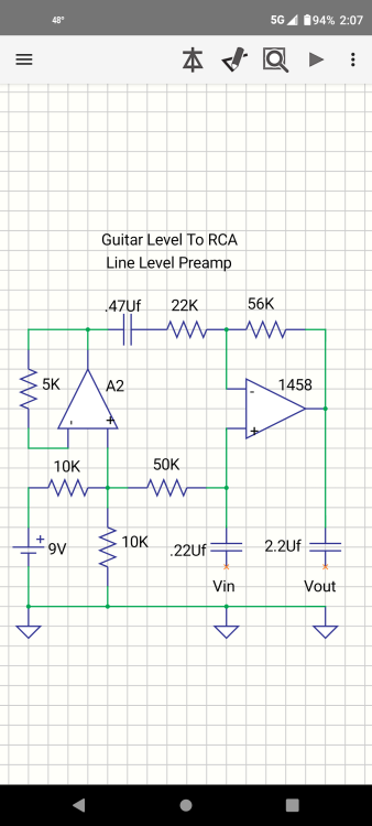
- Earlier
-
anyone?.
-
1. LVDS Interface Specification Forlinx Embedded OK6254-C development board provides 2 x 4-lane LVDS display serial interfaces supporting up to 1.19Gbps per lane; the maximum resolution supported by a single LVDS interface is WUXGA (1920 x 1200@60fps, 162MHz pixel clock). In addition, the interface supports the following three output modes: (1) Single-channel LVDS output mode: at this time, only 1 x LVDS interface displays output; (2) 2x single-channel LVDS (copy) output mode: in this mode, 2 x LVDS display and output the same content; (3) Dual LVDS output mode: 8-lane data and 2-lane clock form the same display output channel.Forlinx Embedded OK6254-C development board is equipped with dual asynchronous channels (8 data, 2 clocks), supporting 1920x1200@60fps. All signals are by default compatible with Forlinx Embedded's 10.1-inch LVDS screen, with a resolution of 1280x800@60fps. 2. Output Mode Setting (1) Single LVDS output mode: We need a single LVDS screen cable. The black port of the cable is connected to the embedded OK6254-C development board, and the white port is connected to the embedded 10.1-inch LVDS display screen. Connection method as shown in the figure below: Note that the red line section corresponds to the triangle position, so don't plug it in wrong. (2) 2x single LVDS (duplicate) output mode: This mode uses the same connections as the Single LVDS Output Mode. Two white ports link to two 10.1-inch LVDS screens from Forlinx Embedded, and a black port on the right connects to the OK6254-C board's LVDS interface for dual-screen display. (3) Dual LVDS output mode: The maximum resolution supported by a single LVDS interface on the OK6254-C development board is WUXGA (1920 x 1200@60fps). To achieve this high-resolution display output, dual LVDS output mode is required. It is worth noting that the connection between the development board and the screen in this mode is the same as in [Single LVDS Output Mode], but the LVDS cable's and the screen's specifications have been improved. 3. Screen Resolution Changing Method OK6254-C development board device tree is easy to modify, we need to open the OK6254-C-lvds.dts (single 8-way configuration) and OK6254-C-lvds-dual.dts (dual 8-way configuration) files. Open OK6254-C-lvds.dts Open OK6254-C-lvds-dual.dts The above figure is the single LVDS and dual LVDS screen resolution information, the default resolution of 1024 * 600, and the maximum resolution support of 1920x1200, you can modify the corresponding parameters according to the Screen User’s Manual. 4. Compilation Configuration Because we only modified the device tree, we don't need a full compilation. After compiling the kernel, a new Image and multiple device tree files will be generated in the images directory. Here we only need to compile the kernel separately. (1) Switch directory: cd OK6254-linux-sdk/ (2) Execution environment variables:.. build.sh (3) Execute the instructions that compile the kernel separately: sudo./build. Sh kernel. (4) Pack all the device tree files to the development board /boot/ directory and replace them, then sync save and reboot scp images/OK6254-C* [email protected]:/boot/ We have modified the corresponding file. How should we select the screen after replacing it? At present, there are three kinds of screen switching control methods: kernel device tree designation, Uboot menu dynamic control, Forlinx Desktop interface and Uboot menu application. Today, I will briefly introduce the dynamic control of Uboot menu. During Uboot, pressing the space bar will take you to the Uboot menu. There are three options in the menu: Enter 0 to enter the Uboot command line; Enter 1 to restart Uboot; Enter 2 to enter the Display Configuration menu. There are three options in the menu: Enter 0 to return to the previous menu; Enter 1 will toggle what option 1 displays to configure Screen 1 LVDS; Note: Screen 1 supports single LVDS, dual LVDS, and off (i.e., LVDS off) Enter 2 to toggle the display of option 2 to configure the Screen 2 LCD. Note: Screen 2 supports 1024 * 600 resolution LCD screen, 800 * 480 resolution LCD screen and off (i.e. RGB off) When selecting the LVDS screen, we enter 1 to select single 8-channel LVDS or dual 8-channel LVDS. After selecting the desired configuration, enter 0 to return to the previous menu level. Restart Uboot or enter the command line to start the system, which can make the screen settings take effect. For other resolution screens, please modify the kernel device tree screen parameters according to the screen parameter requirements.
-
In this blog, I will show you how to integrate an ultra-sonic sensor with ESPHome in home assistant. An ultra sonic sensor is a device that can measure the distance to an object by sending and receiving sound waves. It can be used for various applications, such as obstacle detection, level measurement, parking sensors, etc. What is ESPHome and Home Assistant? ESPHome is a system that allows you to easily create and manage custom firmware for ESP8266 and ESP32 devices. It uses a simple configuration file that defines the components and sensors you want to use and generates the code and binary files for you. You can then upload the firmware to your device using a USB cable or over-the-air (OTA) updates. Home Assistant is an open-source platform that allows you to control and automate your smart home devices. It supports hundreds of integrations with different services and devices, such as lights, switches, sensors, cameras, media players, etc. You can access and control your home assistant from a web browser, a mobile app, or a voice assistant. ESPHome and Home Assistant work very well together, as they can communicate with each other using the native API. This means that you can easily add your ESPHome devices to your home assistant without any extra configuration or coding. You can also use home assistant to monitor and control your ESPHome devices, and create automations based on their states and events. How to Integrate Ultra Sonic Sensor with ESPHome in Home Assistant To integrate an ultra-sonic sensor with ESPHome in home assistant, you will need the following: An ESP8266 or ESP32 device, such as NodeMCU, Wemos D1 Mini, or Xiao ESP32 S3 Sense An ultra sonic sensor, such as HC-SR04 A breadboard and some jumper wires A computer with ESPHome and Home Assistant installed. Get PCBs for Your Projects Manufactured You must check out PCBWAY for ordering PCBs online for cheap! You get 10 good-quality PCBs manufactured and shipped to your doorstep for cheap. You will also get a discount on shipping on your first order. Upload your Gerber files onto PCBWAY to get them manufactured with good quality and quick turnaround time. PCBWay now could provide a complete product solution, from design to enclosure production. Check out their online Gerber viewer function. With reward points, you can get free stuff from their gift shop. Also, check out this useful blog on PCBWay Plugin for KiCad from here. Using this plugin, you can directly order PCBs in just one click after completing your design in KiCad. Let's start with hardware the setup Connect the ultra-sonic sensor to your ESP device using the breadboard and jumper wires. The wiring diagram is shown below: Connect VCC to 5V and GND to Gnd and Trigger to pin 0 and ECHO to pin 1. Home Assistant Setup Next, navigate to the Home Assistant and open the ESPHome. Next, select one of your ESP devices or create a new one. In this case I'm going to use my existing device. Open the yaml file and add these following. sensor: - platform: ultrasonic trigger_pin: 0 echo_pin: 1 name: "Ultrasonic Sensor" update_interval: 2s Then next, click install. and choose your prefer method. I'm going to use wirelessly. Because my device is already connected with my network. Wait until it finishes the upload. Then navigate to the device property and here you can see the Sensor measurement. Next, add the measurement to the dashboard. Conclusion In this blog, I have shown you how to integrate an ultra-sonic sensor with ESPHome in home assistant. This is a simple and effective way to use an ultra-sonic sensor in your smart home projects. You can also use other types of sensors and components with ESPHome and home assistant and create your own custom firmware and integrations. I hope you found this blog helpful and informative. If you have any questions or feedback, please leave a comment below. Thank you for reading!
-
can someone tell me how to connect an external rectifier to this?,i have one like an alluminium block with one corner chamfered representing + out from the bridge,can anyone tell me what points to connect what place on the pcb to,a pic would be best,thanks Paul l.
-
I am starting to build this,the kit came with tl081 opamps,i have some LF357n and some ua748cp opamps,what would be best to use?,thanks in advance.
-

pcDuino to Act as 3D printer Control PC
piropa replied to Linksprite-Yuki's topic in Theory articles
Yes exactly, You said it right. Today you see how much 3d printing serves on daily basis. It's perfect guide, thank you! So of the best 3d printers list can be found here portable printers wireless for travel, they are doing fantastic work in reviewing top products. I'm quite impressed. -
Jeezus H!!! Spectrophotometers, amplitude and frequency modulation, gigowillits, reverse bridge rectifiers, etc. Just shine a light on it!!!
-
 Thanks for sharing the project. Here is another good project based on DHT11. This is done with ESP8266. But it can be done with ESP32 too. This is a room-temperature monitor. We can use it to monitor our room from anywhere in the world with dht11: https://www.pcbway.com/project/shareproject/Room_Temperature_Over_Internet_With_BLYNK_ESP8266_DHT11_91b0d3f5.html
 -
 Get started quickly and master the recommendations and steps for building and configuring a LoRaWAN network Learn the basics: First, understand the basic principles and concepts of LoRa and LoRaWAN. LoRa is a physical layer modulation technology, and LoRaWAN is a wireless network protocol built on LoRa technology. Understand the working principle of the LoRaWAN network, including the communication process and protocol specifications between terminal devices, gateways and network servers. Choose the right hardware: Choose appropriate LoRa modules, gateways and development boards based on project needs. Generally speaking, you can choose a commonly used LoRa module (such as Semtech SX1276), LoRa gateway and development board for learning and practice. Build LoRaWAN network: Configure the LoRaWAN gateway: Connect the LoRaWAN gateway to the Internet and configure the network, including the address, port and key to connect to the network server. Configure the network server: Build a LoRaWAN network server in the cloud or locally, and configure the authentication information and data transmission parameters of the terminal device. Register the terminal device: Register the EUI and application key of the terminal device and add it to the LoRaWAN network. Write the application: Use corresponding development tools and programming languages (such as Arduino, Python, etc.) to write applications for terminal devices. Realize the data collection, transmission and processing functions of terminal equipment, and implement corresponding data processing and control logic according to application requirements. Testing and Debugging: Deploy the LoRaWAN network in a real environment and perform functional testing and performance evaluation. Use debugging tools and log information to locate and solve possible problems to ensure network stability and reliability. Learn and communicate: Join the LoRaWAN developer community or forum to learn and share experiences, tips and tutorials. Attend relevant training courses or online tutorials to improve your skills and knowledge.
 -
As engineering vehicles become smarter, onboard dashboards and 360°surround view systems are now standard configuration. The onboard dashboard monitors vehicle status in real-time, while the 360° surround view system offers a complete view of the surroundings, helping drivers better get the vehicle’s surroundings. To meet market demand and enhance the safety performance and operational efficiency of engineering vehicles, we offer the following solutions: onboard dashboard and 360° surround view system for engineering vehicles. Function Description: Real-time Monitoring: Through the onboard dashboard, drivers can instantly access the operational status of engineering vehicles, such as engine speed, vehicle speed, hydraulic oil pressure, etc. Simultaneously, the 360° surround view system can instantly collect image data of the vehicle's surrounding environment, offering a comprehensive perspective to assist drivers in better understanding their surroundings. Data Display and Interaction: The on-board instrument panel has a clear and intuitive interface, which can display various data and information. Drivers can interact with the instrument panel through the touch screen or other input devices to achieve information inquiry, parameter setting, and other functions. Remote Monitoring and Diagnosis: Through the communication module, this solution can achieve communication with the remote monitoring center, upload the vehicle operation status data and image data of the 360° Around View system, and receive remote control commands. This helps the management personnel conduct remote management of vehicles and improve operation efficiency. Stability and Reliability: Both the hardware and software designs of this solution possess high stability and reliability, enabling them to operate stably for a long time in complex vehicle environments without being prone to malfunctions or damage. Easy to Operate and Maintain: This solution offers drivers seamless usage with minimal maintenance costs. Forlinx Embedded recommends the FETT507-C SoM as a hardware solution. Here are the optimizations and extensions of the solution: 1. Support for AHD Analog High-definition Cameras: The FETT507-C SoM integrates AHD analog high-definition camera input and adopts the MIPI_CSI solution to enable signal acquisition from four AHD analog cameras. This not only provides a comprehensive view but also assists drivers in better understanding the surroundings of the vehicle, thereby enhancing driving safety. 2. Stable CAN Data Acquisition: By utilizing a stable and mature SPI-to-CAN conversion solution, real-time vehicle operational data can be collected, providing robust support for vehicle monitoring and data analysis. 3. Flexible Expansion with Multiple Interfaces: Supporting the I2C interface allows for convenient integration of audio chips for in-vehicle audio data acquisition or connection to other external sensors. Additionally, it supports four display output interfaces including RGB, LVDS, HDMI, and CVBS, with a maximum display resolution of 4K, meeting the display needs of different sizes and resolutions. 4. Communication and Positioning Capabilities: The FETT507-C SoM integrates GPS and 4G modules to enable daily vehicle communication, remote access, and positioning functions, providing support for remote vehicle monitoring. 5. Real-time Video Stream Storage: The SoM supports external SD card connection for real-time video stream storage, facilitating easy playback and data analysis. 6. GPIO Interface and Button Functionality: The provision of GPIO interfaces caters to various physical button function requirements, facilitating user operation and control. 7. Support for Multiple Operating Systems: The FETT507-C system on module supports various operating systems, including Linux 4.9 and Android 10.0, offering users greater possibilities for further development.
-
In this blog, I will show you how to set a static IP address on Xiao ESP32 S3 Sense, a tiny but powerful microcontroller board with Wi-Fi and Bluetooth capabilities. Setting a static IP address can be useful if you want to access your ESP32 web server or other network services using the same IP address, even after restarting the board. What is a Static IP Address? An IP address is a unique identifier for a device on a network. It consists of four numbers separated by dots, such as 192.168.1.100. A static IP address is an IP address that does not change, unlike a dynamic IP address that is assigned by a router or a DHCP server. Advantages Easier to remember and access. More reliable and stable connection Less prone to IP conflicts or errors Disadvantages More difficult to configure and maintain. Less flexible and scalable More vulnerable to security risks Therefore, you should only use a static IP address if you have a specific need for it, and if you are aware of the potential drawbacks. Get PCBs for Your Projects Manufactured You must check out PCBWAY for ordering PCBs online for cheap! You get 10 good-quality PCBs manufactured and shipped to your doorstep for cheap. You will also get a discount on shipping on your first order. Upload your Gerber files onto PCBWAY to get them manufactured with good quality and quick turnaround time. PCBWay now could provide a complete product solution, from design to enclosure production. Check out their online Gerber viewer function. With reward points, you can get free stuff from their gift shop. Also, check out this useful blog on PCBWay Plugin for KiCad from here. Using this plugin, you can directly order PCBs in just one click after completing your design in KiCad. How to Set a Static IP Address on Xiao ESP32 S3 Sense To set a static IP address on Xiao ESP32 S3 Sense, you will need the following: A Xiao ESP32 S3 Sense board A micro-USB cable. A computer with Arduino IDE installed. A Wi-Fi network with internet access The steps are as follows: Connect the Xiao ESP32 S3 Sense board to your computer using the micro-USB cable. Open the Arduino IDE and select the correct board and port from the Tools menu. Obtain the current network settings of your ESP32 board by uploading the following sketch. Before uploading, make sure to replace the ssid and password variables with your actual Wi-Fi network credentials. #include <WiFi.h> const char* ssid = "YourNetworkName"; const char* password = "YourPassword"; void setup() { Serial.begin(115200); Serial.print("Connecting to "); Serial.println(ssid); WiFi.begin(ssid, password); while (WiFi.status() != WL_CONNECTED) { delay(1000); Serial.print("."); } Serial.println(""); Serial.println("Connected..!"); Serial.print("Current ESP32 IP: "); Serial.println(WiFi.localIP()); Serial.print("Gateway (router) IP: "); Serial.println(WiFi.gatewayIP()); Serial.print("Subnet Mask: " ); Serial.println(WiFi.subnetMask()); Serial.print("Primary DNS: "); Serial.println(WiFi.dnsIP(0)); Serial.print("Secondary DNS: "); Serial.println(WiFi.dnsIP(1)); } void loop() { } System Response Open the Serial Monitor and set the baud rate to 115200. Then, press the EN button on the ESP32 board. It may take a few moments to connect to your network, after which it will print the current network settings of the ESP32 board to the serial monitor. Take note of these settings, especially the IP address, gateway, subnet mask, and DNS servers. Choose a static IP address for your ESP32 board that is within the same subnet as your router but does not conflict with any other devices on your network. For example, if your router’s IP address is 192.168.1.1 and your subnet mask is 255.255.255.0, you can choose any IP address from 192.168.1.2 to 192.168.1.254, as long as it is not already taken by another device. You can check the IP addresses of other devices on your network using tools such as Fing or Advanced IP Scanner. Modify the previous sketch by adding the following lines before the WiFi.begin() function. Replace the staticIP, gateway, subnet, primaryDNS, and secondaryDNS variables with your chosen static IP address and the network settings you obtained in step 4. // Static IP configuration IPAddress staticIP(192, 168, 1, 100); // ESP32 static IP IPAddress gateway(192, 168, 1, 1); // IP Address of your network gateway (router) IPAddress subnet(255, 255, 255, 0); // Subnet mask IPAddress primaryDNS(192, 168, 1, 1); // Primary DNS (optional) IPAddress secondaryDNS(0, 0, 0, 0); // Secondary DNS (optional) // Configures static IP address if (!WiFi.config(staticIP, gateway, subnet, primaryDNS, secondaryDNS)) { Serial.println("STA Failed to configure"); } Upload the modified sketch to your ESP32 board and open the Serial Monitor again. You should see that your ESP32 board has successfully connected to your network using the static IP address you specified. You can now access your ESP32 web server or other network services using the static IP address. For example, if you have uploaded the ESP32 Web Server example sketch, you can open a web browser and type the static IP address in the address bar. You should see the web page that allows you to control the GPIO pins of your ESP32 board. Home Assistance with ESP32 Cam Apart from controlling the LED's we can implement this on ESP32 Cam Webserver. Now you can use the static IP in the home assistance. Add you can stream your camera footage. #include "esp_camera.h" #include <WiFi.h> // // WARNING!!! PSRAM IC required for UXGA resolution and high JPEG quality // Ensure ESP32 Wrover Module or other board with PSRAM is selected // Partial images will be transmitted if image exceeds buffer size // // You must select partition scheme from the board menu that has at least 3MB APP space. // Face Recognition is DISABLED for ESP32 and ESP32-S2, because it takes up from 15 // seconds to process single frame. Face Detection is ENABLED if PSRAM is enabled as well // =================== // Select camera model // =================== //#define CAMERA_MODEL_WROVER_KIT // Has PSRAM //#define CAMERA_MODEL_ESP_EYE // Has PSRAM //#define CAMERA_MODEL_ESP32S3_EYE // Has PSRAM //#define CAMERA_MODEL_M5STACK_PSRAM // Has PSRAM //#define CAMERA_MODEL_M5STACK_V2_PSRAM // M5Camera version B Has PSRAM //#define CAMERA_MODEL_M5STACK_WIDE // Has PSRAM //#define CAMERA_MODEL_M5STACK_ESP32CAM // No PSRAM //#define CAMERA_MODEL_M5STACK_UNITCAM // No PSRAM //#define CAMERA_MODEL_AI_THINKER // Has PSRAM //#define CAMERA_MODEL_TTGO_T_JOURNAL // No PSRAM #define CAMERA_MODEL_XIAO_ESP32S3 // Has PSRAM // ** Espressif Internal Boards ** //#define CAMERA_MODEL_ESP32_CAM_BOARD //#define CAMERA_MODEL_ESP32S2_CAM_BOARD //#define CAMERA_MODEL_ESP32S3_CAM_LCD //#define CAMERA_MODEL_DFRobot_FireBeetle2_ESP32S3 // Has PSRAM //#define CAMERA_MODEL_DFRobot_Romeo_ESP32S3 // Has PSRAM #include "camera_pins.h" // =========================== // Enter your WiFi credentials // =========================== // Replace with your network credentials const char* ssid = "xxxxxxx"; const char* password = "xxxxxxx"; // Set web server port number to 80 WiFiServer server(80); // Variable to store the HTTP request String header; // Set your Static IP address IPAddress local_IP(192, 168, 1, 162); // Set your Gateway IP address IPAddress gateway(192, 168, 1, 1); IPAddress subnet(255, 255, 0, 0); IPAddress primaryDNS(8, 8, 8, 8); //optional IPAddress secondaryDNS(8, 8, 4, 4); //optional void startCameraServer(); void setupLedFlash(int pin); void setup() { Serial.begin(115200); Serial.setDebugOutput(true); Serial.println(); camera_config_t config; config.ledc_channel = LEDC_CHANNEL_0; config.ledc_timer = LEDC_TIMER_0; config.pin_d0 = Y2_GPIO_NUM; config.pin_d1 = Y3_GPIO_NUM; config.pin_d2 = Y4_GPIO_NUM; config.pin_d3 = Y5_GPIO_NUM; config.pin_d4 = Y6_GPIO_NUM; config.pin_d5 = Y7_GPIO_NUM; config.pin_d6 = Y8_GPIO_NUM; config.pin_d7 = Y9_GPIO_NUM; config.pin_xclk = XCLK_GPIO_NUM; config.pin_pclk = PCLK_GPIO_NUM; config.pin_vsync = VSYNC_GPIO_NUM; config.pin_href = HREF_GPIO_NUM; config.pin_sccb_sda = SIOD_GPIO_NUM; config.pin_sccb_scl = SIOC_GPIO_NUM; config.pin_pwdn = PWDN_GPIO_NUM; config.pin_reset = RESET_GPIO_NUM; config.xclk_freq_hz = 20000000; config.frame_size = FRAMESIZE_UXGA; config.pixel_format = PIXFORMAT_JPEG; // for streaming //config.pixel_format = PIXFORMAT_RGB565; // for face detection/recognition config.grab_mode = CAMERA_GRAB_WHEN_EMPTY; config.fb_location = CAMERA_FB_IN_PSRAM; config.jpeg_quality = 12; config.fb_count = 1; // if PSRAM IC present, init with UXGA resolution and higher JPEG quality // for larger pre-allocated frame buffer. if(config.pixel_format == PIXFORMAT_JPEG){ if(psramFound()){ config.jpeg_quality = 10; config.fb_count = 2; config.grab_mode = CAMERA_GRAB_LATEST; } else { // Limit the frame size when PSRAM is not available config.frame_size = FRAMESIZE_SVGA; config.fb_location = CAMERA_FB_IN_DRAM; } } else { // Best option for face detection/recognition config.frame_size = FRAMESIZE_240X240; #if CONFIG_IDF_TARGET_ESP32S3 config.fb_count = 2; #endif } #if defined(CAMERA_MODEL_ESP_EYE) pinMode(13, INPUT_PULLUP); pinMode(14, INPUT_PULLUP); #endif // camera init esp_err_t err = esp_camera_init(&config); if (err != ESP_OK) { Serial.printf("Camera init failed with error 0x%x", err); return; } sensor_t * s = esp_camera_sensor_get(); // initial sensors are flipped vertically and colors are a bit saturated if (s->id.PID == OV3660_PID) { s->set_vflip(s, 1); // flip it back s->set_brightness(s, 1); // up the brightness just a bit s->set_saturation(s, -2); // lower the saturation } // drop down frame size for higher initial frame rate if(config.pixel_format == PIXFORMAT_JPEG){ s->set_framesize(s, FRAMESIZE_QVGA); } #if defined(CAMERA_MODEL_M5STACK_WIDE) || defined(CAMERA_MODEL_M5STACK_ESP32CAM) s->set_vflip(s, 1); s->set_hmirror(s, 1); #endif #if defined(CAMERA_MODEL_ESP32S3_EYE) s->set_vflip(s, 1); #endif // Setup LED FLash if LED pin is defined in camera_pins.h #if defined(LED_GPIO_NUM) setupLedFlash(LED_GPIO_NUM); #endif // Configures static IP address if (!WiFi.config(local_IP, gateway, subnet, primaryDNS, secondaryDNS)) { Serial.println("STA Failed to configure"); } // Connect to Wi-Fi network with SSID and password Serial.print("Connecting to "); Serial.println(ssid); WiFi.begin(ssid, password); while (WiFi.status() != WL_CONNECTED) { delay(500); Serial.print("."); } // Print local IP address and start web server Serial.println(""); Serial.println("WiFi connected."); Serial.println("IP address: "); Serial.println(WiFi.localIP()); startCameraServer(); Serial.print("Camera Ready! Use 'http://"); Serial.print(WiFi.localIP()); Serial.println("' to connect"); } void loop() { // Do nothing. Everything is done in another task by the web server delay(10000); } Conclusion In this blog, I have shown you how to set a static IP address on Xiao ESP32 S3 Sense, a tiny but powerful microcontroller board with Wi-Fi and Bluetooth capabilities. Setting a static IP address can be useful if you want to access your ESP32 web server or other network services using the same IP address, even after restarting the board. However, you should also be aware of the potential disadvantages and risks of using a static IP address, and only use it if you have a specific need for it. I hope you found this blog helpful and informative. If you have any questions or feedback, please leave a comment below. Thank you for reading!
-
 Had some time this weekend and a desire to create something new and interesting, so went ahead and created an Arduino/NodeMCU based indoor dial thermometer. This device displays the temperature in degree centigrade on a D-Shaped Gauge as well as on a 7-Segment display. In addition to that, it also saves the temperature and humidity readings in a MySQL DataBase hosted on a home based Raspberry Pi Server. The data is then displayed using the "Our Smart Home" app. Awards This project got featured on Cults3D and Instructables https://cults3d.com/en/3d-model/gadget/arduino-based-indoor-dial-thermometer https://www.instructables.com/NodeMCU-Based-3D-Printed-Indoor-Gauge-Thermometer/ Components Required For this project we need: 2 x TM1637 Display Modules 1 x DHT22 or DHT11 Module 1 x NodeMCU Microcontroller 1 x 28BYJ-48 Stepper Motor with ULN2003 Driver Board 1 x 10K Resistor A 3D Printer Copper Wire and Some Nuts & Bolts Circuit Diagram The circuit is very simple. Connect the ULN2003 driver board’s IN1, IN2, IN3 and IN4 to the NodeMCUs digital pins D0, D1, D2 and D3. Then connect the OUT Pin of the DHT22 to the D5 Pin of NodeMCU. After that connect the 2 x Display Modules to the microcontroller. We are going to use a Common Clock Pin D4 for both modules. Then connect the DIO of one of the modules to D6 (TEMP) and the other one to D7 (HUM) pins on the NodeMCU. Important: Please avoid using the boot config pins D3, D4, D8 and the RTC pin D0 for the displays. Now, on the D8 Pin we are going to connect the switch. This switch has a very important role in this circuit. This switch acts as the 'home' or the 'starting point' of the stepper motor. When the switch is open Pin D8 is connected to GND through the pull-down resistor and we read a LOW. When the switch is closed, Pin D8 connects to 3.3v pin of NodeMCU and we read a HIGH. When the 'temperature changes' or the 'device boots up', the pointer starts moving 'counterclockwise'. As soon as the pointer hits the home position, Pin D8 reads HIGH and the logic moves the pointer 'clockwise' to display the temperature on the gauge as read by the DHT22 module. The Code The code starts by including all the necessary libraries. Then it defines all the variables needed for setting up the WiFi connection. Next, it assigns a static IP address to the ESP8266 (if you want to use DHCP then go ahead and delete these three lines from the code). After that, it sets up the 2 x URLs that are needed for updating the heartbeat, temperature and humidity. String URLUpdateStatus = "http://192.168.0.7/Arduino/Weather/UpdateStatus.php"; String URLUpdateTemp = "http://192.168.0.7/Arduino/Weather/UpdateTemperature.php"; Before going ahead let's have a quick look at the 2 php files. The "UpdateStutus.php" file uses an UPDATE query to update the timestamp of the device sending the request to the current epoch time and hence updating the heartbeat. <?PHP try { $Token = $_GET["Token"]; $Location = $_GET["Location"]; include "ConnectionStringArduino.php"; // Create connection $sql = 'Update `Status` SET `DateTime`=\''.time().'\',`State`=\'1\' WHERE `Device`=\''.$Location.'\' AND `Token` = \''.$Token.'\';'; $result = $con->query( $sql ); if($result === FALSE) { die(mysqli_error());} mysqli_close($con); } catch (Exception $e) {} ?> The "UpdateTemperature.php" uses an INSERT query to add a new row to the database with the current values of Temperature and Humidity. <?PHP try { $Location = $_GET["Location"]; $TEMP = $_GET["TEMP"]; $HUM = $_GET["HUM"]; include "ConnectionStringArduino.php"; // Create connection $sql = "INSERT INTO `Weather` (`DateTime`,`Temperature`,`Humidity`,`Location`) VALUES ('".time()."','".$TEMP."','".$HUM."','".$Location."');"; $result = $con->query( $sql ); if($result === FALSE) { die(mysqli_error());} mysqli_close($con); } catch (Exception $e) {} ?> This is what is written to the database and can be displayed using Google Charts, in my case, I am using the "Our Smart Home" app to display the data using php and JavaScript. Currently I am only displaying the data from the Study room and the Peg Box. To know more about my award winning "Peg Box" project please have a look at my electronics tutorial no. 34 "Peg Box with Temperature and Humidity Monitor using NodeMCU" (https://youtu.be/elH331NXPsU). After that, I am defining all the variables required for reading and storing the value of temperature and humidity. Next, I am defining all the variables and setting up any additional symbols required for displaying temperature and humidity on the TM1637 Display Module. After that, I am defining the D8 pin of the NodeMCU as the reset switch pin. We will talk about this in detail in the following sections. Next, I am setting up the Steps Per Revolution of the stepper motor as 2038 and then initializing the stepper library through pins D0 to D3. const int stepsPerRevolution = 2038; // Change this to fit the number of steps per revolution of your motor Stepper myStepper(stepsPerRevolution, D0, D2, D1, D3);// Initialize the stepper library on pins D0 through D3 One thing to note: since I need both clockwise and counterclockwise movements, I have to initialize the pins in the order shown on screen. Then in the setup() section, first I am setting up the WiFi connection and then sending a heartbeat to the server. Then I am setting up the brightness of the 7-Segments to their max values followed by starting the dht module and finally setting the pin-mode of the switch to INPUT. void setup() { Serial.begin(115200); // Initialize the serial port /*********** Setup a WiFi connection ***********/ if (WiFi.config(local_IP, gateway, subnet)) { Serial.println("Static IP Configured"); } else { Serial.println("Static IP Configuration Failed"); }; WiFi.mode(WIFI_STA); WiFi.begin(WIFI_SSID, WIFI_PWD); while (WiFi.status() != WL_CONNECTED) { delay(500); Serial.print("."); }; Serial.println("\nWiFi connected"); Serial.print("IP address: "); Serial.println(WiFi.localIP()); SendIamAlive(); // Send the initial wakeup message to the server /**********************************************/ display_TMP.setBrightness(7); // Set the display brightness (0-7) display_HUM.setBrightness(7); // Set the display brightness (0-7) dht.begin(); // Setup the DHT sensor pinMode(SWITCH, INPUT); // Declare the switch pin as input }; Now, in the loop() section I am reading the temperature using the Read_Temp() function and then sending the Temperature and Humidity values every 30 minutes and heartbeat every minute to the home server. void loop() { /** Read the temp and humidity info from ther sensor and display it on the 7-segmnet and Gauge **/ Read_Temp(); /** Sending Humidity and temperature every 30 minutes **/ if((millis() - lastTime) > timerDelay){ Serial.println("Sending Temp and Humidity");SendTemperatureAndHumidity(); lastTime = millis(); }; /** Sending I am alive message every minute **/ if((millis() - StatusCounter) > 60000){ Serial.println("Sending Heartbeat"); SendIamAlive(); StatusCounter = millis(); }; }; Next, you see the definition of the SendIamAlive() and SendTemperatureAndHumidity() functions which utilizes the WiFiConnect() function to send the values using the previously discussed URLs. The Read_Temp() function reads the temperature and humidity and updates the 7-Segment displays and moves the pointer only if there is a change in the values. The Move_Needle() function first sends the pointer to the home position using the Return_Home() function and then looks through and moves the pointer to the correct position until the stepCout is = STEPS. The value of STEPS is calculated based on the "stepsPerRevolution" which we previously set it up as 2038. So, 2038 / 2 (for half circle) = 1019 Now by dividing 1019 by 180 degrees we get the steps required to display each degree centigrade. Now to display each degree centigrade we need 180/60 = 3 divisions. Since our gauge starts from -10 and not 0 we also have to add the first 10 blocks which is (5.661 * 10 * 3) to our calculation. int STEPS = (5.661 * 3 * TEMP) + 169.833; // 5.661 (step resolution) * 3 (steps to display each °C) * TEMP + 169.833 (5.661 * 10 * 3) = since it starts from -10 and not 0) That's it as easy as that. 3D Designing Lets have a quick look at the 3D model of the project. At the front, we have The Pointer, D-Shaped Dial, and the Temperature Scale on the dial. Down at the bottom we have the Enclosure that will house the microcontroller and all other electronics components in it. The enclosure has a Lid to keep the electronic components safe and sound. At the back, we have a pocket to hold the DHT22 Module, 3 x holes for the stepper motor, 2 x groves for the TM1637 Display Module and 2 x L-Shaped Brackets to hold the top Dial to the bottom Enclosure. 3D Printing Once the 3D models were sorted, it was time for me to fire up my 3D printing oven and start printing these 3D models. I used: - 1.75mm Cold White PLA Filament, and printed the models with - 0.2mm - with 0% infill - and with support. As we all know, 3D printing is the process that uses computer-aided design or CAD, to create objects layer by layer. 3D printing is not a new technology, it's been there since the 1980's, when Charles W. Hull invented the process and created the first 3D-printed part. Since then, the field of 3D printing has grown exponentially and holds countless possibilities. The 3D printing process fascinates me a lot and I sometimes love to sit near my printer and watch these layers getting printed. The entire printing process took a little over 5 hours to complete and this is the final result. Alright now, let's start gluing all the printed parts. I first superglued the L-Shaped Brackets to the dial followed by the pocket that will hold the DHT22 module. Then, I went ahead and screwed the bottom enclosure to the top section via the L-Shaped Brackets. Breadboard Demo Before adding the electronic bits to the 3D printed bits, let's do a quick test to make sure everything works as expected. So, this 7-Segment display is displaying the temperature and the other one is displaying the humidity. The needle is currently going round and round in circles as it has no idea where to stop. To stop the needle, and to send it the correct position on the gauge, I need to connect this red jumper cable connected to 3.3v to the D8 Pin of the NodeMCU. Once I short the cable, the needle changes its direction and moves clockwise to display the temperature value read from the DHT22 module. The temperature and humidity values are also sent to the 'Home Server' which are then displayed using the "Our Smart Home" app. Coloring Using Acrylic colors, I painted all the 3D printed parts of the project. Assembling Once the coloring is done, its now time for me to put all the electronic components together. First I screwed the stepper motor to the back of the dial. Then, I gently pushed the DHT22 Module into its pocket at the back of the dial. Now the interesting bit. As per our previous discussion, we are going to use a copper wire as a switch that will move the pointer to its correct position. The copper wire will be fed through these two holes from the back and will loop through this small pipe like structure in the front. A small cut will be made on the top exposed side of the copper wire. Now on the pointer, we need to add a small piece of copper wire. When this copper bit touches the two copper wires on the pipe, it will complete the circuit and will send a HIGH to the system. Next, I am hot gluing the two TM1637 7-Segment Display Modules to the back of the dial. Once done, it's pretty much just a matter of soldering all the sensors to the NodeMCU as per our circuit diagram. Final Demo So, this is how my final setup looks like. Once the device is turned on, the pointer moves counterclockwise until it touches the copper wires that acts like a switch. Upon touching the wires the pointer moves clockwise to display the temperature value read from the DHT22 module on the D-Shaped Gauge. The temperature and humidity values are also displayed using 7-Segment Displays. The values are also sent over WiFi to a Raspberry Pi Home Server and stored in a MySQL database. Using google charts, you can display the data using various different graph options. In my case, I am using the "Our Smart Home" app to display the data using php and JavaScript. Thanks for watching, please comment and let me know if there are any scopes of improvement. Thanks Thanks again for checking my post. I hope it helps you. If you want to support me subscribe to my YouTube Channel: https://www.youtube.com/user/tarantula3 Video: Watch Full Blog Post: Visit Thermometer STLs: Download Peg Box: Watch How To Wire A Pushbutton: View Stepper Motor Specs: View Support My Work BTC: 1Hrr83W2zu2hmDcmYqZMhgPQ71oLj5b7v5 LTC: LPh69qxUqaHKYuFPJVJsNQjpBHWK7hZ9TZ DOGE: DEU2Wz3TK95119HMNZv2kpU7PkWbGNs9K3 ETH: 0xD64fb51C74E0206cB6702aB922C765c68B97dCD4 BAT: 0x9D9E77cA360b53cD89cc01dC37A5314C0113FFc3 LBC: bZ8ANEJFsd2MNFfpoxBhtFNPboh7PmD7M2 COS: bnb136ns6lfw4zs5hg4n85vdthaad7hq5m4gtkgf23 Memo: 572187879 BNB: 0xD64fb51C74E0206cB6702aB922C765c68B97dCD4 MATIC: 0xD64fb51C74E0206cB6702aB922C765c68B97dCD4 Thanks, ca gain in my next tutorial.
 -
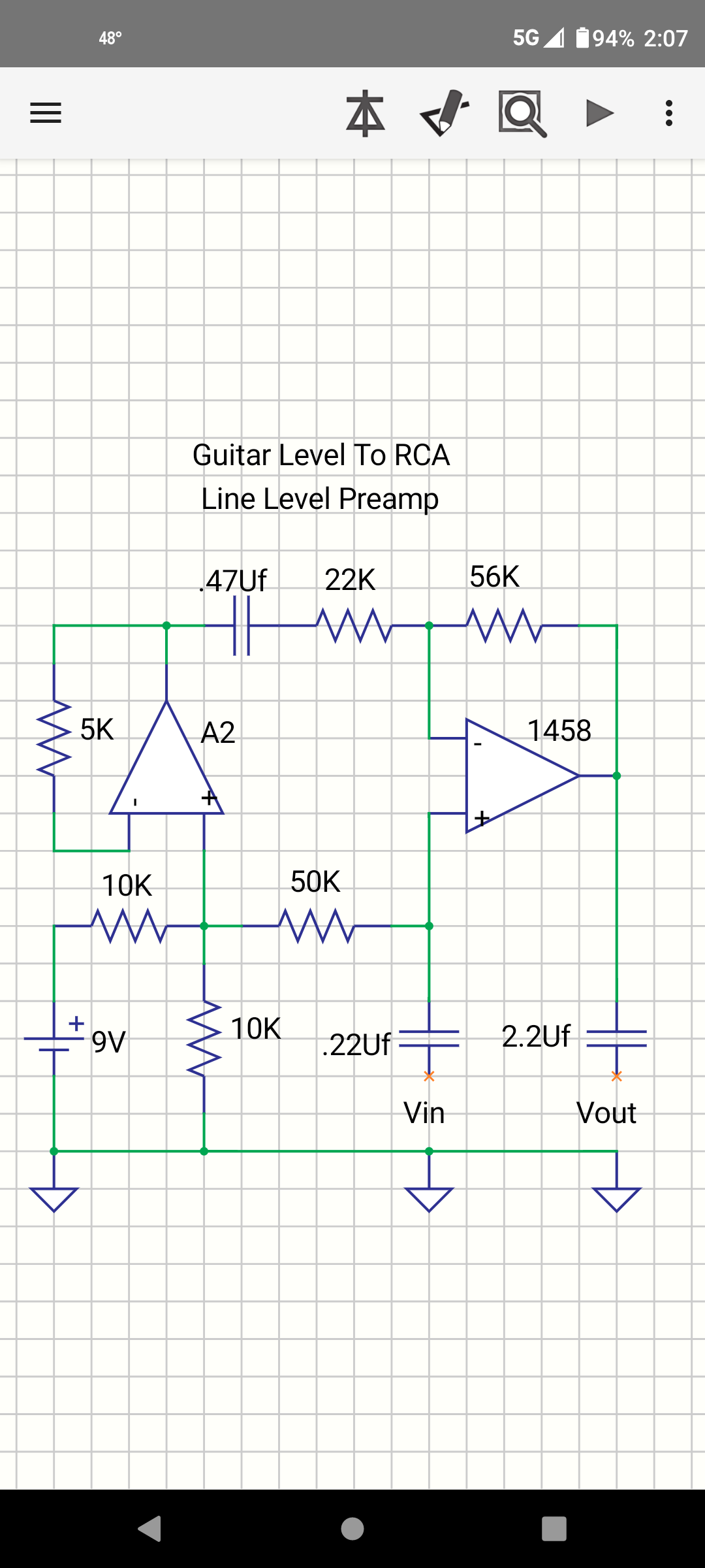
Guitar Level To RCA Line Level Preamp
Paul Bober replied to Paul Bober's topic in Electronic Projects Design/Ideas
This circuit brings up the -20 decibel guitar level signal to -10 decibels, which is what is required by RCA Line Level Inputs. These Inputs are found on P.A., D.J., and Home Stereo Equipment. Do not confuse RCA Line Level Inputs with 600 ohm balanced Line Level Inputs, which are also on P.A. , and D.J. equipment. The 600 ohm balanced Line Level Inputs, require an input of +4 decibels, as opposed to -10 decibels. Voltage gain of my circuit=.909×((1+(56,000/22,000)). 3.222 as shown. ( 10.16 decibels ). This is because 9.1% of my audio input signal, is buffered and applied to the inverting input of the op amp marked as 1458. A2 is the 2nd half of the 1458 op amp package. A2 also provides a buffered version, of 1/2 the supply voltage, as a ground potential for the op amp marked 1458. See schematic. Should there be any noise, on the output of the D.C. power supply, the noise divides by two, where the 10K resistors meet. That noise is coupled through the 50K resistor to the non inverting input on 1458. The noise is also buffered by A2, and applied to the inverting input on 1458. With equal amounts of noise on both inputs, there is no potential difference in noise to be amplified. Last but not least, do not connect the audio output of this circuit, to phono inputs, microphone inputs, or 600 ohm line inputs.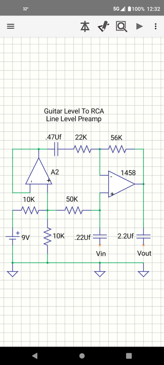
-

Guitar Level To RCA Line Level Preamp
admin replied to Paul Bober's topic in Electronic Projects Design/Ideas
Thanks for sharing your schematic. Could you give us a little more info on what this does? -
I hope that my schematic is useful, for Guitar Players, Hobbyists, Electronics Engineering Instructors/Students. The audio output of this circuit, connects to the RCA Line Level Inputs, found on P.A. , D.J. , and Home Stereo Equipment.

-
Dust is an open source of pollution due to dust on the ground, human-driven and driven to fly into the atmosphere, and is an important part of the total ambient air. Suspended particulate matter in the ambient air lasts for a long time and can be inhaled. Once the inhalable particulate enters the human body, it will accumulate in the respiratory system and cause many diseases, which is harmful to human beings. Dust monitoring is a real-time on-line monitoring measure to prevent and control air pollution. The dust monitoring equipment can monitor the atmospheric particulate matter concentration, PM value, temperature, humidity, wind speed, wind direction and other data in real time, and the dust pollution can be prevented and rectified in time by means of real-time data monitoring and alarm. The online monitoring system can save a lot of manpower and material resources and provide quantitative data support for on-site treatment and administrative enforcement. After the online monitoring system is installed, continuous and uninterrupted monitoring will be carried out. It mainly monitors respirable particulate matter and is complemented by a video monitoring system, a noise monitoring system, a meteorological system, a data acquisition system, and a communication system. The online automatic monitoring system is mainly used for online dust, environmental protection, meteorological station, tunnel and other online dust monitoring, unorganized smoke and dust pollution source emissions, residential areas, commercial areas, road traffic, construction areas, etc.; online real-time automatic monitoring of ambient air quality, and can obtain evidence through the camera. The real-time data from the weather station monitoring and the tunnel subway station can be transmitted to the data platform in time through the wired or wireless network for easy management and control. System Components The system consists of a data collector, a sensor, a video monitoring system (optional), a wireless transmission system, a background data processing system and an information monitoring management platform. The monitoring sub-station integrates various functions such as atmospheric PM1.0, PM2.5, PM10 monitoring, ambient temperature and humidity and wind speed and direction monitoring, noise monitoring, video surveillance (optional), etc.; the data platform is a networked platform with Internet architecture, which has the monitoring function of each sub-station and various functions such as alarm processing, recording, querying, statistics, report output, etc. of the data. The system can also be linked with various pollution control devices to achieve the purpose of automatic control. Implementation Scheme The online dust monitoring host can be developed using the FETMX6ULL-C SoM recommended by Forlinx Embedded. Hardware Design: FETMX6ULL-C SoM supports 8 x RS232/RS485/TTL and multi-channel I/O interfaces, which can be connected to dust sensors and other environmental monitoring equipment. At the same time, the industrial design enables it to operate stably in harsh outdoor environment, which ensures the reliability of the monitoring system. Network Communication: FETMX6ULL-C System on Module supports 2 x dual 100m Ethernet and standard TCP/IP and UDP protocol stacks. Monitoring data can be transmitted to the monitoring center or cloud server in real time through the network to realize remote monitoring and management. Wireless Communication: It supports 4G and WiFi wireless communication, and after a long time of stable testing, it can ensure the stable transmission of monitoring data, and even in the absence of wired network, it can also realize the online monitoring function. Screen Display: FETMX6ULL-C supports a variety of LCD screen designs, which enables the monitoring system to select the appropriate display screen according to actual needs, and realize the intuitive display and operation of data. Based on the features of Forlinx Embedded FETMX6ULL-C SoM, the dust online monitoring realization solution can achieve the advantages of rich hardware interfaces, stable network communication, flexible software support, etc. It is suitable for a variety of environmental monitoring scenarios and can meet the needs of the industrial level to guarantee the stability and reliability of the monitoring system.
-
 Thanks for sharing it, I appreciate you.
 -
BreanneJJustice reacted to a post in a topic:
How to Support Virtual Network on Linux 4.1.15?
-
Command 1. The video recording was unsuccessful with the command ffmpeg -framerate 25 -f v4l2 -i /dev/video4 recording1.mp4 . According to the official ffmpeg documentation, -r and -framerate have the same function, but the actual test shows that they are different. -framerate is used to limit the input while -r is used to limit the output 2. Video can be recorded with the command ffmpeg -r 25 -f v4l2 -i /dev/video4 recording1.mp4 , but problems such as frame error and frame repetition will occur. 3. Use ffmpeg -f v4l2 -r 25 -thread_queue_size 128 -i /dev/video4 -vcodec libx264 -b:v 800k-preset ultrafast recording1.mp4 to achieve dual camera video recording at the same time. Parameter Description: ⚫ -f Set the output format, the output format is v412 frame (The commands found earlier all use the framework avfoundation, a full-featured framework for handling multimedia data on iOS, macOS, watchOS, and tvOS. The v412 framework used in this command is a framework for video device drivers in the Linux kernel, which provides a unified interface to the application layer and supports flexible expansion of various complex hardware). ⚫ -r Set frame rate, set frame rate to 25fbs. ⚫ -thread_queue_size (The thread _ queue _ size is applied to the first input specified after it. The term "thread_queue_size" can be applied to all inputs and determines at the application level. How many packets from that input can be queued while waiting for ffmpeg to receive and process them on its main thread. A few capture devices, primarily dshow, use "rtbufsize" to store incoming frames while waiting for them to be transferred to the application-level queue for that input. These two options do not adjust the value of the other, so they should be set manually. The default is 8. Common Warnings: Thread message queue blocking; consider raising the thread_queue_size option (current value: 8). To solve this problem, the official explanation: This option sets the maximum number of packets queued when reading from a file or device. (In low-latency/high-rate real-time streams, packets may be dropped if they are not read in a timely manner; increasing this value prevents this.) ⚫ -i Set input stream, set input from video4 ⚫ -vcodec Set the video encoder,(-vcodec and-codec:v equal in value) Encoders are library files that implement a certain encoding format. Encoding and decoding of video/audio in a certain format can only be achieved if an encoder for that format is installed. Here are some of FFmpeg's built-in video encoders. libx264: The most popular open source H.264 encoder NVENC: NVIDIA GPU-based H.264 encoder libx265: Open source HEVC encoder libvpx: Google's VP8 and VP9 encoders libaom:AV1 Encoder ⚫ -B:v Video bit rate ⚫ -preset specifies the output video quality, which will affect the file generation speed. The following values are available: Ultrafast,superfast,veryfast,faster,fast,medium,slow,slower,veryslow,placebo from fast to slow, the ultrafast transcoding rate is the fastest, and the video is often the most blurred. ⚫ recording1.mp4 Name and file type of the output videoYou can use ffmpeg-formats to get all the file types supported by ffmpeg, where the annotation before the file is as follows: D.=Demuxing supported(Support for video/audio encapsulation) .E=Muxing supported(Support decapsulation of video/audio) Method: Software: ⚫ Ubuntu: 1.Devepoment board networking 2. sudo apt-gat update upgrades apt-gat to the latest version (optional) 3. sudo apt-get install ffmpeg uses apt-gat to obtain ffmpeg 4. Enter relevant commands Hardware: Connect the Forlinx self-made analog camera module to support two cameras. Video4-7 are nodes generated by the TVIN, with the upper left corresponding to video7, lower left corresponding to video6, lower right corresponding to video5, and upper right corresponding to video4. Select according to the actual situation.
-
 Streaming ESP32-CAM Video to Home Assistant The ESP32-CAM is a versatile and affordable camera module that can be used for various projects. In this tutorial, we’ll explore how to set up video streaming from the ESP32-CAM to Home Assistant, allowing you to monitor your surroundings remotely. Setting Up Video Streaming Web Server Open the Arduino IDE and navigate to the ESP32 examples. 1. Select File->Examples->ESP32->Camera->CameraWebServer example in Arduino IDE. 2. Replace the codes in CameraWebServer with the code below (Note: please fill in your WiFi account and password) #include "esp_camera.h" #include <WiFi.h> // // WARNING!!! PSRAM IC required for UXGA resolution and high JPEG quality // Ensure ESP32 Wrover Module or other board with PSRAM is selected // Partial images will be transmitted if image exceeds buffer size // // You must select partition scheme from the board menu that has at least 3MB APP space. // Face Recognition is DISABLED for ESP32 and ESP32-S2, because it takes up from 15 // seconds to process single frame. Face Detection is ENABLED if PSRAM is enabled as well // =================== // Select camera model // =================== #define PWDN_GPIO_NUM -1 #define RESET_GPIO_NUM -1 #define XCLK_GPIO_NUM 45 #define SIOD_GPIO_NUM 1 #define SIOC_GPIO_NUM 2 #define Y9_GPIO_NUM 48 #define Y8_GPIO_NUM 46 #define Y7_GPIO_NUM 8 #define Y6_GPIO_NUM 7 #define Y5_GPIO_NUM 4 #define Y4_GPIO_NUM 41 #define Y3_GPIO_NUM 40 #define Y2_GPIO_NUM 39 #define VSYNC_GPIO_NUM 6 #define HREF_GPIO_NUM 42 #define PCLK_GPIO_NUM 5 #include "DFRobot_AXP313A.h" DFRobot_AXP313A axp; // =========================== // Enter your WiFi credentials // =========================== const char* ssid = "*****"; const char* password = "******"; void startCameraServer(); void setup() { Serial.begin(115200); Serial.setDebugOutput(true); Serial.println(); while(axp.begin() != 0){ Serial.println("init error"); delay(1000); } axp.enableCameraPower(axp.eOV2640);//Enable the power for camera camera_config_t config; config.ledc_channel = LEDC_CHANNEL_0; config.ledc_timer = LEDC_TIMER_0; config.pin_d0 = Y2_GPIO_NUM; config.pin_d1 = Y3_GPIO_NUM; config.pin_d2 = Y4_GPIO_NUM; config.pin_d3 = Y5_GPIO_NUM; config.pin_d4 = Y6_GPIO_NUM; config.pin_d5 = Y7_GPIO_NUM; config.pin_d6 = Y8_GPIO_NUM; config.pin_d7 = Y9_GPIO_NUM; config.pin_xclk = XCLK_GPIO_NUM; config.pin_pclk = PCLK_GPIO_NUM; config.pin_vsync = VSYNC_GPIO_NUM; config.pin_href = HREF_GPIO_NUM; config.pin_sscb_sda = SIOD_GPIO_NUM; config.pin_sscb_scl = SIOC_GPIO_NUM; config.pin_pwdn = PWDN_GPIO_NUM; config.pin_reset = RESET_GPIO_NUM; config.xclk_freq_hz = 20000000; config.frame_size = FRAMESIZE_UXGA; config.pixel_format = PIXFORMAT_JPEG; // for streaming //config.pixel_format = PIXFORMAT_RGB565; // for face detection/recognition config.grab_mode = CAMERA_GRAB_WHEN_EMPTY; config.fb_location = CAMERA_FB_IN_PSRAM; config.jpeg_quality = 12; config.fb_count = 1; // if PSRAM IC present, init with UXGA resolution and higher JPEG quality // for larger pre-allocated frame buffer. if(config.pixel_format == PIXFORMAT_JPEG){ if(psramFound()){ config.jpeg_quality = 10; config.fb_count = 2; config.grab_mode = CAMERA_GRAB_LATEST; } else { // Limit the frame size when PSRAM is not available config.frame_size = FRAMESIZE_SVGA; config.fb_location = CAMERA_FB_IN_DRAM; } } else { // Best option for face detection/recognition config.frame_size = FRAMESIZE_240X240; #if CONFIG_IDF_TARGET_ESP32S3 config.fb_count = 2; #endif } #if defined(CAMERA_MODEL_ESP_EYE) pinMode(13, INPUT_PULLUP); pinMode(14, INPUT_PULLUP); #endif // camera init esp_err_t err = esp_camera_init(&config); if (err != ESP_OK) { Serial.printf("Camera init failed with error 0x%x", err); return; } sensor_t * s = esp_camera_sensor_get(); // initial sensors are flipped vertically and colors are a bit saturated if (s->id.PID == OV3660_PID) { s->set_vflip(s, 1); // flip it back s->set_brightness(s, 1); // up the brightness just a bit s->set_saturation(s, -2); // lower the saturation } // drop down frame size for higher initial frame rate if(config.pixel_format == PIXFORMAT_JPEG){ s->set_framesize(s, FRAMESIZE_QVGA); } #if defined(CAMERA_MODEL_M5STACK_WIDE) || defined(CAMERA_MODEL_M5STACK_ESP32CAM) s->set_vflip(s, 1); s->set_hmirror(s, 1); #endif #if defined(CAMERA_MODEL_ESP32S3_EYE) s->set_vflip(s, 1); #endif WiFi.begin(ssid, password); WiFi.setSleep(false); while (WiFi.status() != WL_CONNECTED) { delay(500); Serial.print("."); } Serial.println(""); Serial.println("WiFi connected"); startCameraServer(); Serial.print("Camera Ready! Use 'http://"); Serial.print(WiFi.localIP()); Serial.println("' to connect"); } void loop() { // Do nothing. Everything is done in another task by the web server delay(10000); } Then upload the code to the FireBeetle ESP32 S3 board and look for the serial terminal response. Get PCBs for Your Projects Manufactured You must check out PCBWAY for ordering PCBs online for cheap! You get 10 good-quality PCBs manufactured and shipped to your doorstep for cheap. You will also get a discount on shipping on your first order. Upload your Gerber files onto PCBWAY to get them manufactured with good quality and quick turnaround time. PCBWay now could provide a complete product solution, from design to enclosure production. Check out their online Gerber viewer function. With reward points, you can get free stuff from their gift shop. Also, check out this useful blog on PCBWay Plugin for KiCad from here. Using this plugin, you can directly order PCBs in just one click after completing your design in KiCad. Setting Up Video Stream Properties Next, open up the IP address that shows in the serial terminal and look for the camera web server properties. Set up the resolution. Go with the lower one to get a high FPS. Finally, add the:81/stream in the camera IP address. Now it will directly show you the camera feed. Integrating with Home Assistant Open Home Assistant. Next, navigate to the overview and add a picture card. Enter the IP address of your ESP32-CAM following:81/stream and click Finish. And that’s it! You’ve successfully set up video streaming from the ESP32-CAM to Home Assistant. Feel free to customize and enhance this project further. Happy monitoring! 📷🏠