Leaderboard
Popular Content
Showing content with the highest reputation on 05/24/2018 in Posts
-

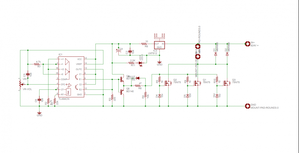
750W DC Motor Speed Controler 0-100% with Schematic and PCB Layout
davidjackson reacted to Youkito1991 for a topic
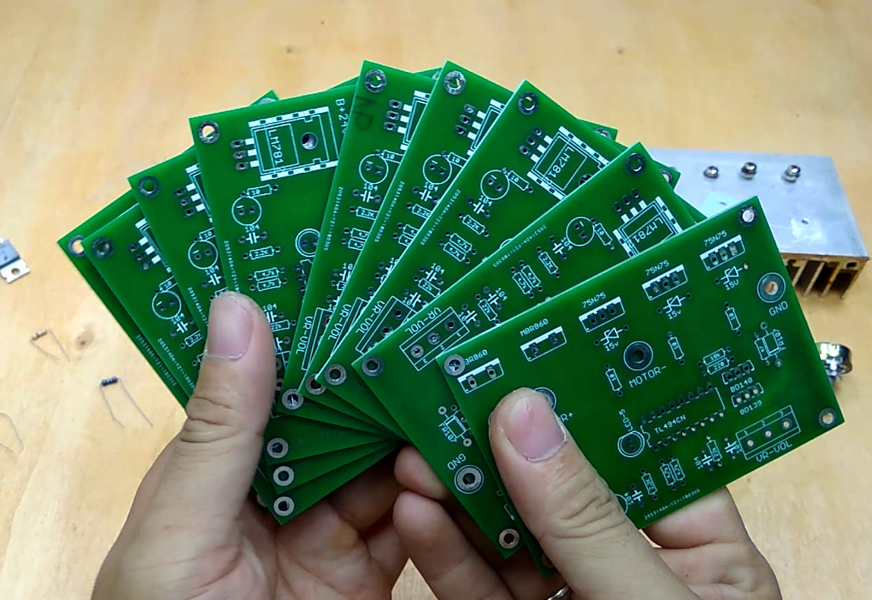
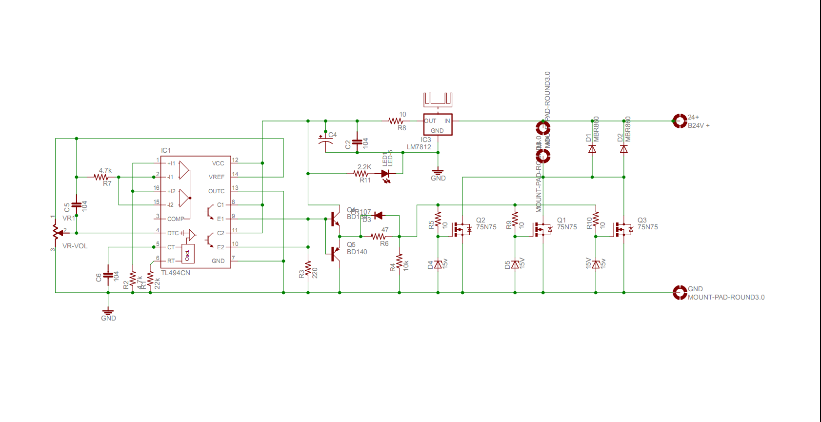
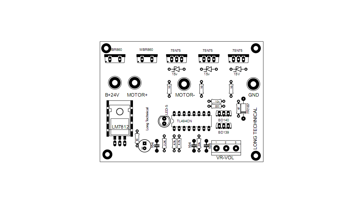
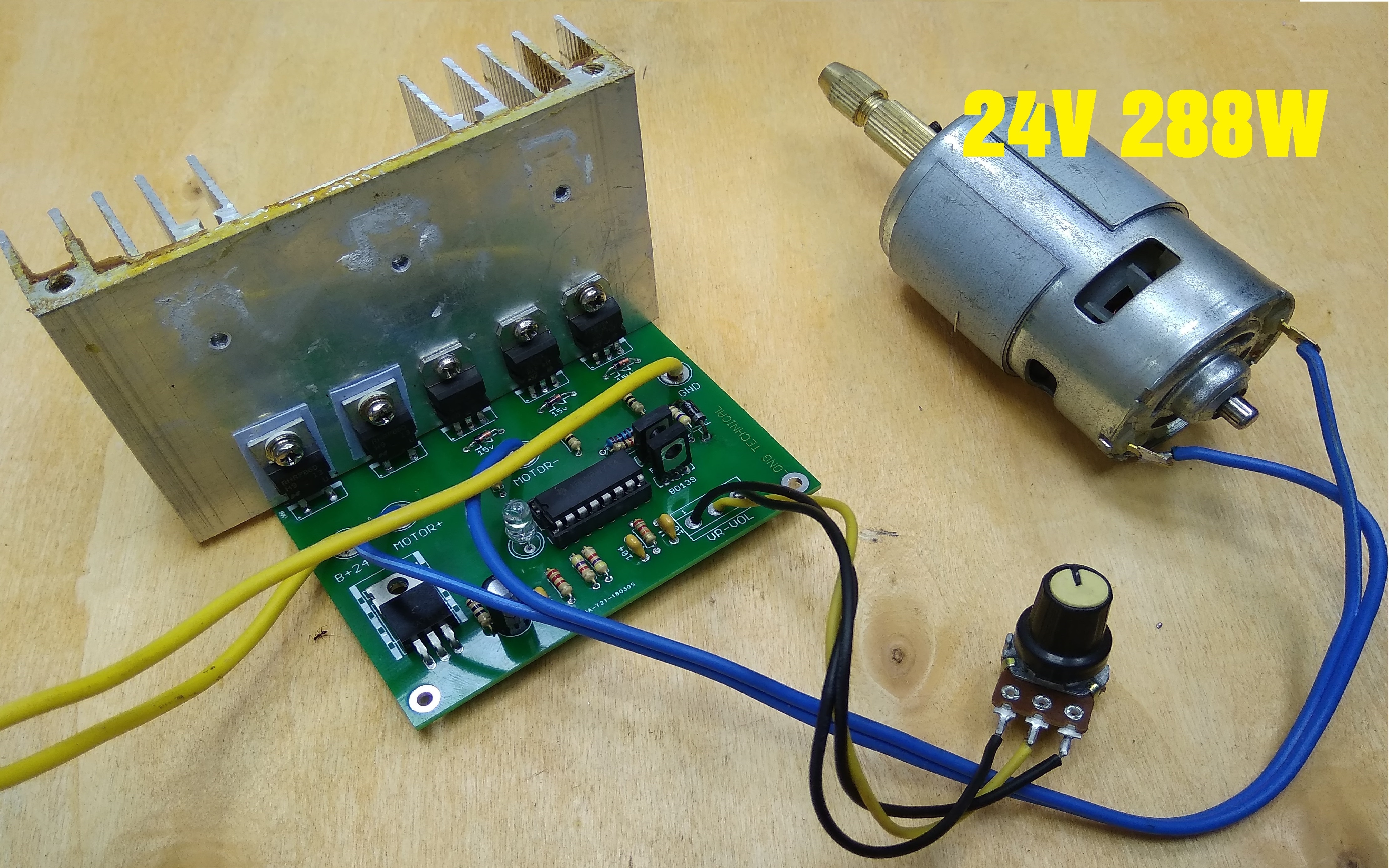
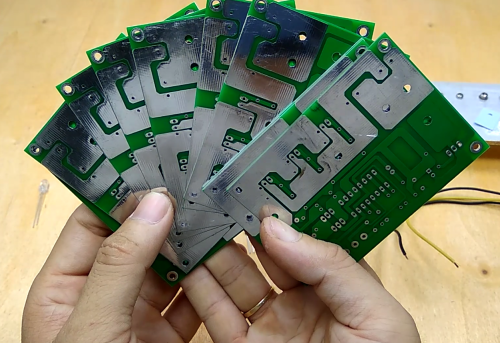
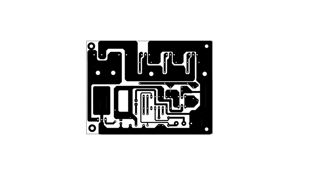
Introduction ---------------- Hi Friends, I am a newcomer. I try to make 750w DC 24V DC motor speed control. At my project i use TL494 ( ka7500) for control the motor, the current increase by 3 mosfet IRF75n75 ( IFR3205) you can use the biger mosfet for get big power. At this video i show you how to i make it. I don't have the big motor so i use 288W 24V 775 motor for test. You can see the result on my video. The circuit run very well. The total cost of the project is around $10 - $15. Step 1 Hardware Requirement You can see all of my project but i will show again Step 2 Make the PCB You can make the PCB use iron method. I have post the Shematic and PCB file. Please download bellow. Or you can order PCB online like me, i order PCB online from JLCPCB.COM. Their price is very low only 2$/10PCB with high quality. I order PCB from their lot of time. You can try. Look the PCB i had order, what do you think about that ? Step 3 Make the PCB The Schematic and layout file. you can download PDF file below and make it at home by yourself. Step 3 Finsh and Get Big Motor Controler I am a newcomer and this is the fist time i post on this forums. If i have any mistake please comment below i will try to fix in the next project. I want to share you all of thing i know. If you have any question for my project, please comment below i will help you. You can find more project about electrical on my youtube channel: https://www.youtube.com/c/LongTechnical Thank you very much 750W_DC_Motor_Controller_TOP PCB.pdf 750W_DC_Motor_Controller_SCH.pdf 750W_DC_Motor_Controller_PCB.pdf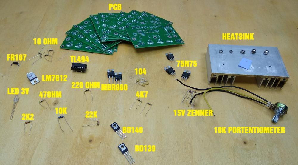


 1 point
 -

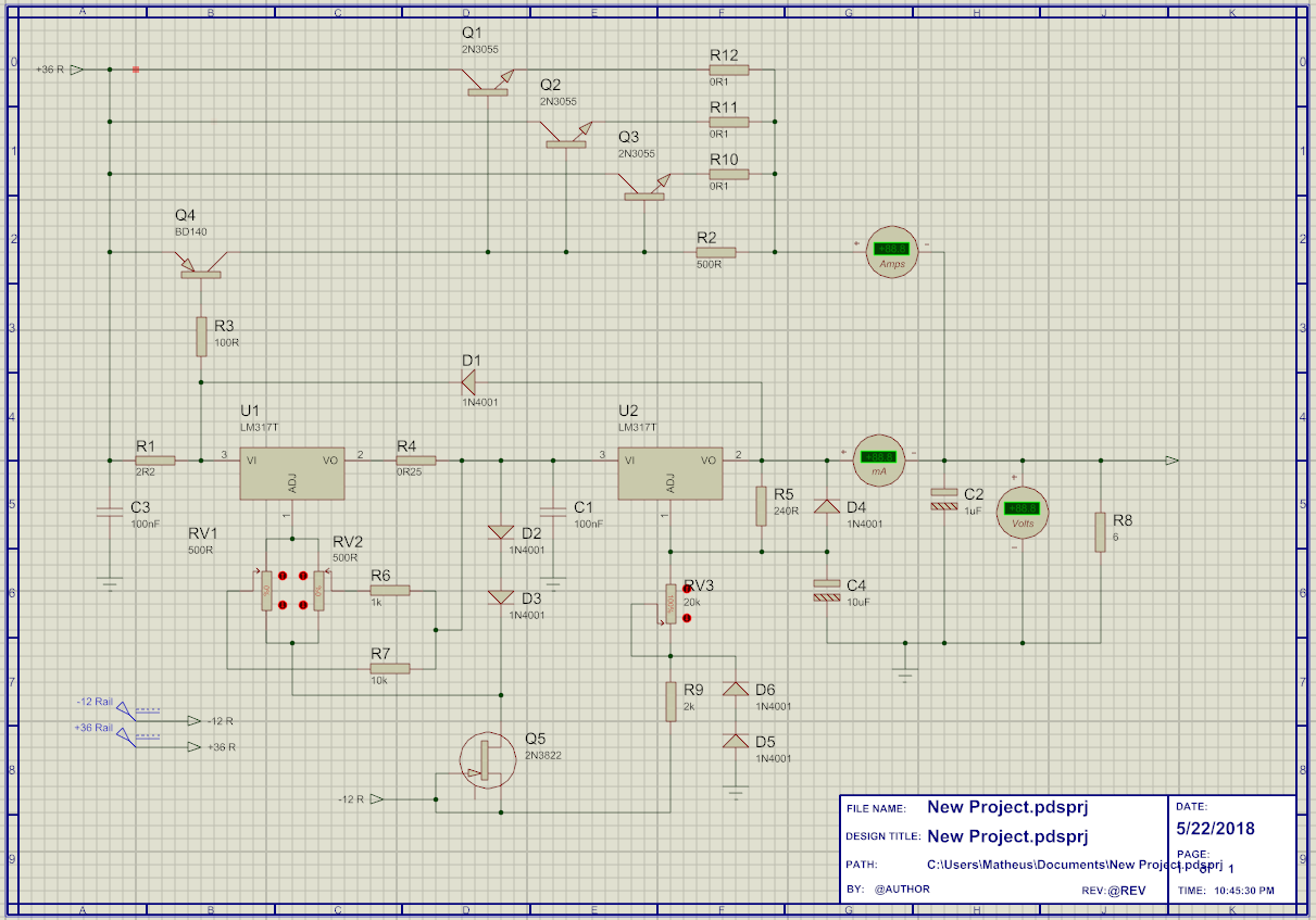
In need of a great bench power supply
davidjackson reacted to Bortmoun for a topic
Hi there. I need a good bench power supply, which i want to build myself, for my hobby lab. The thing is, i have been thinking about LM-317 as my linear voltage regulator (and because here where i live i don't have no access to better ones). The design must have these features: a)Current control from few mA to 5A b)Voltage control from 0V to 30V. For this purpose I've built this schematic, which i attached here. Please, tell me what you think about this project or if does work or does not, for i am a beginner in these things. R8 is just a dummy load. The things i need help: 1) How can i add a minimum load (10 mA as by LM-317 datasheet) to keep the power supply operating in different potentials? 2) I need a replacement for 2n3822, i can't find it in my country too. 3) Can I run it from a fixed switched power supply (way more cheaper than buying a transformer here)? 4) In the future, I'm thinking about adding digital control with PWM to this circuit with Arduino or something like that. Do you think this is feasible? Thanks in advance and sorry for my English. PS: i have already looked here in this forum about the 0-30v power supply with op amps, but i really like the LM-317 concept, although i will build this last one if my project fails. 1 point