Leaderboard
Popular Content
Showing content with the highest reputation since 07/27/2015 in all areas
-

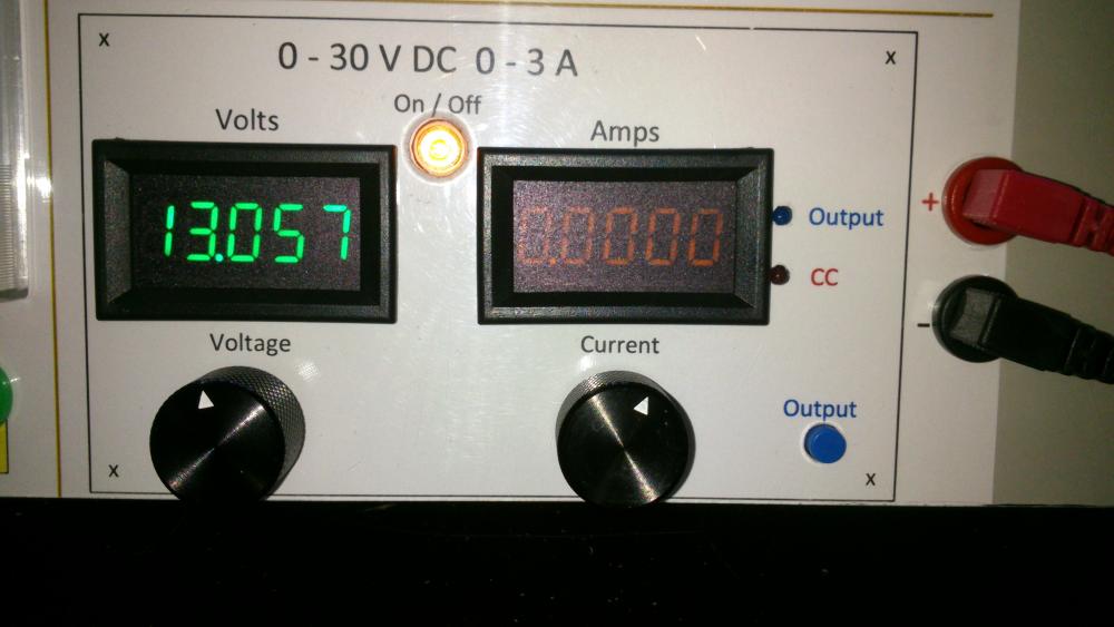
0-30V 0-3A Latest Data
AsSa and 3 others reacted to repairman2be for a topic
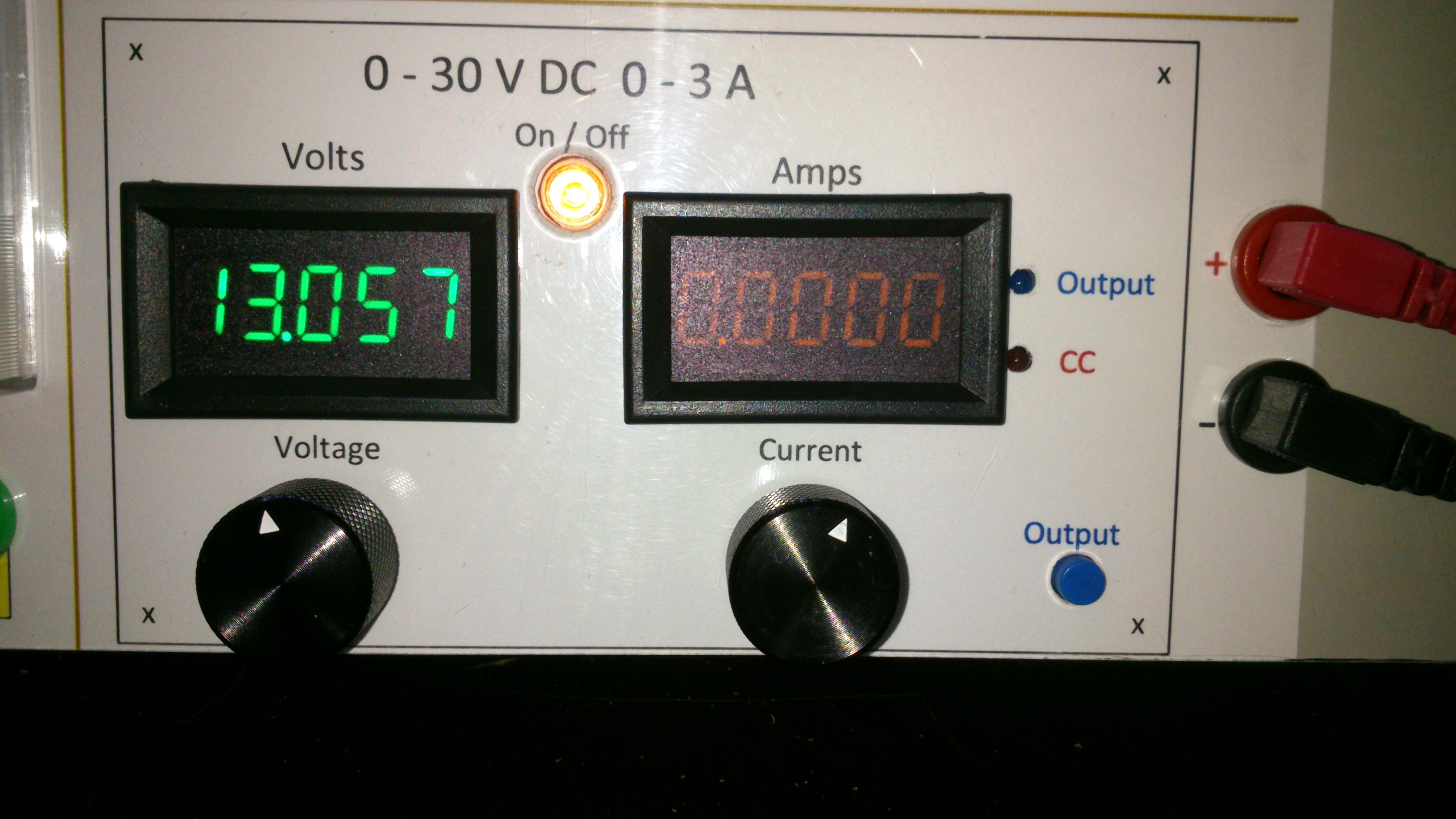
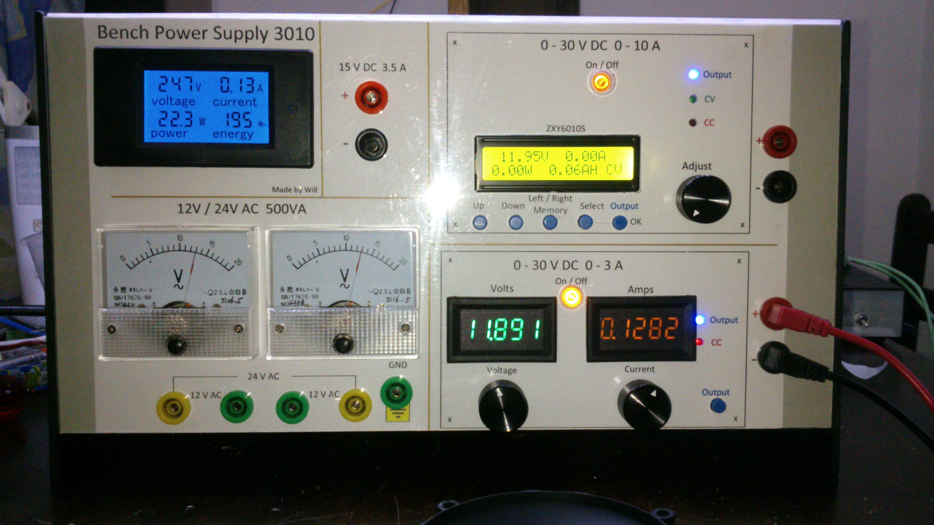
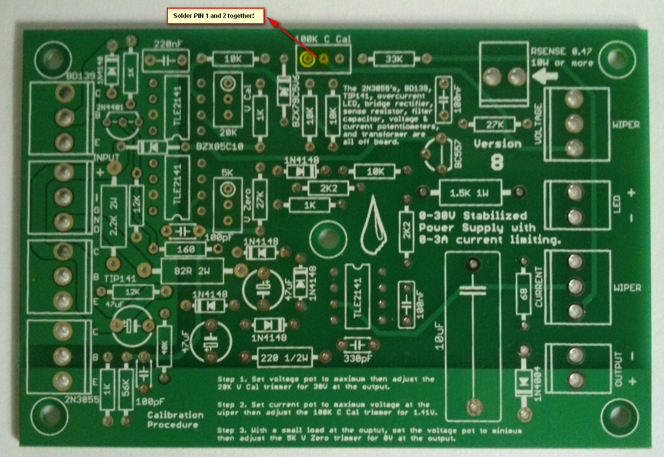
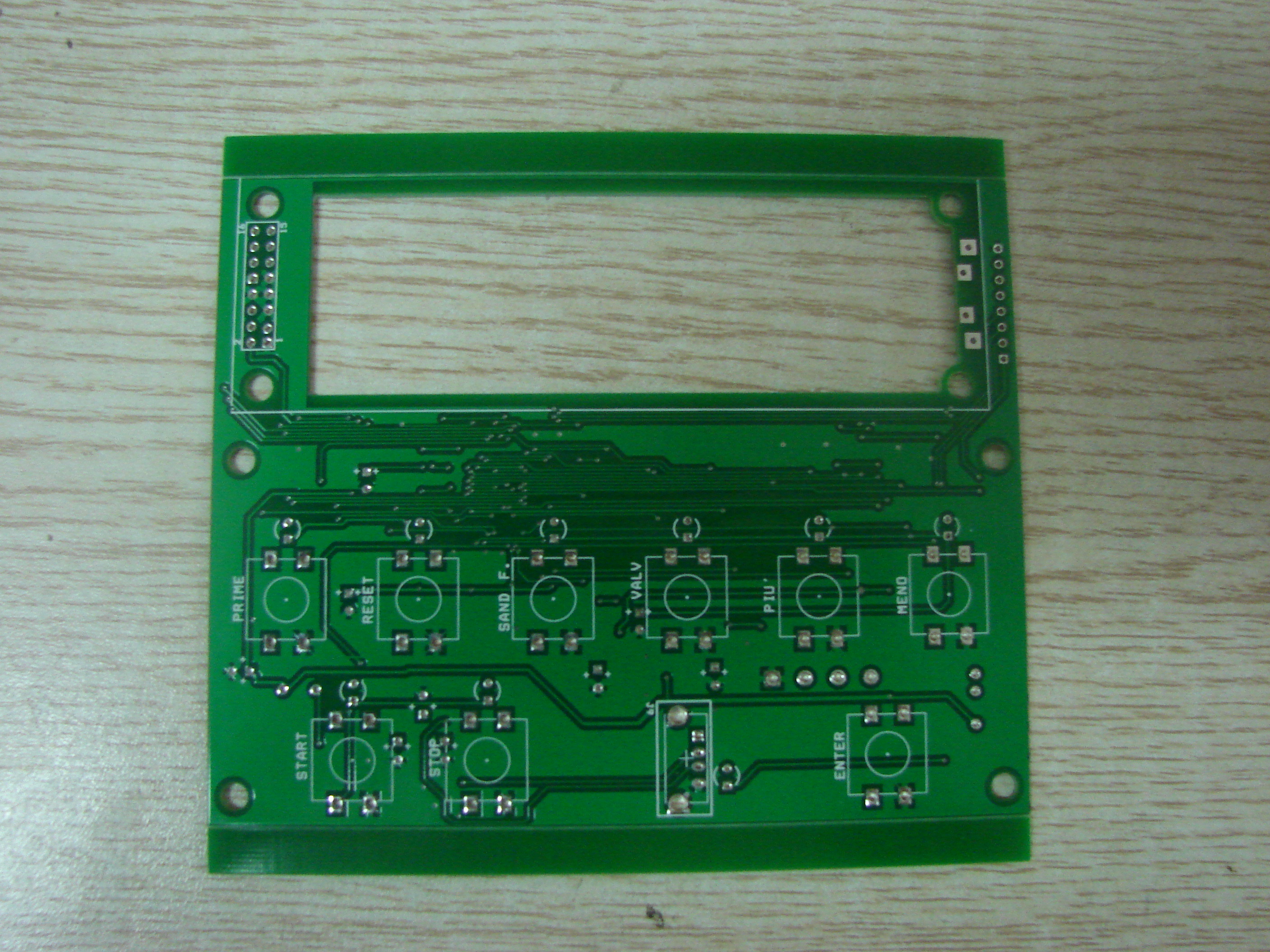
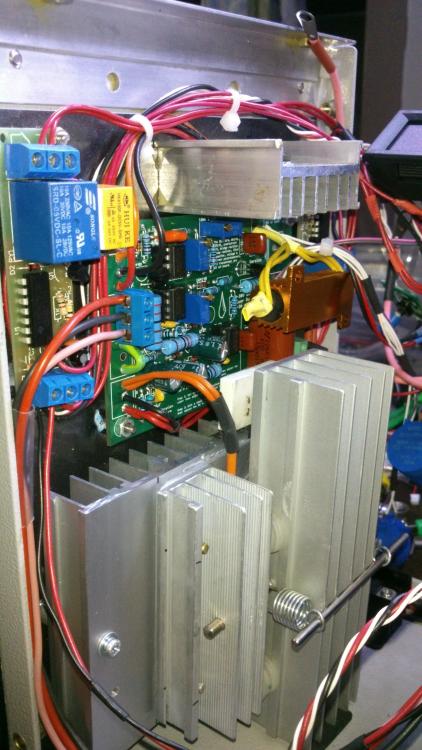
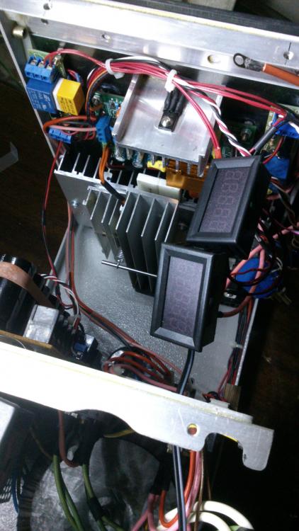
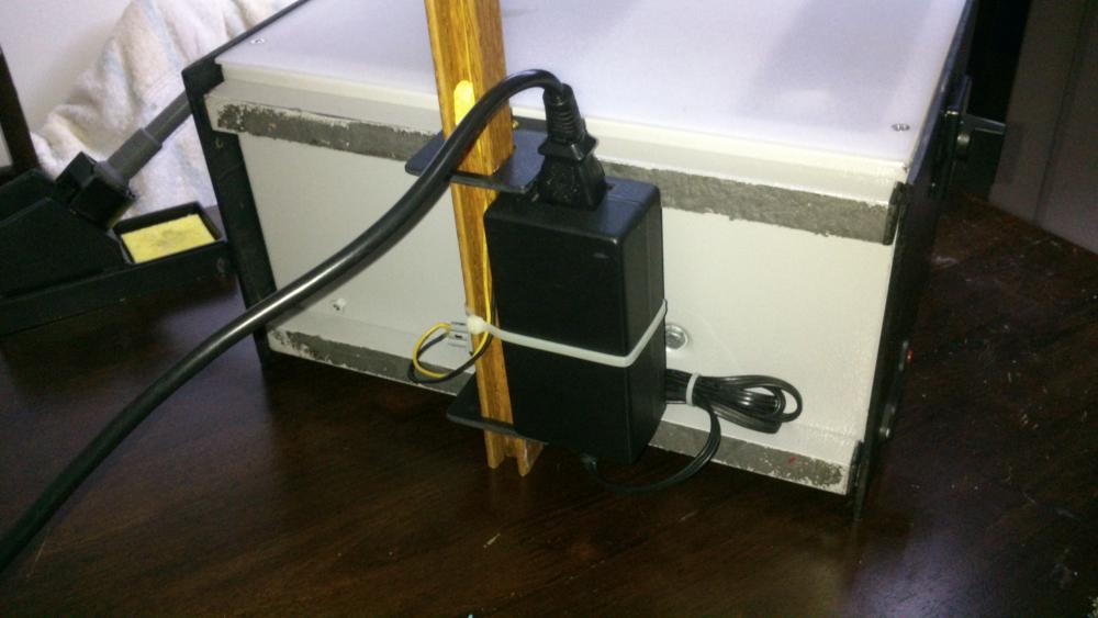
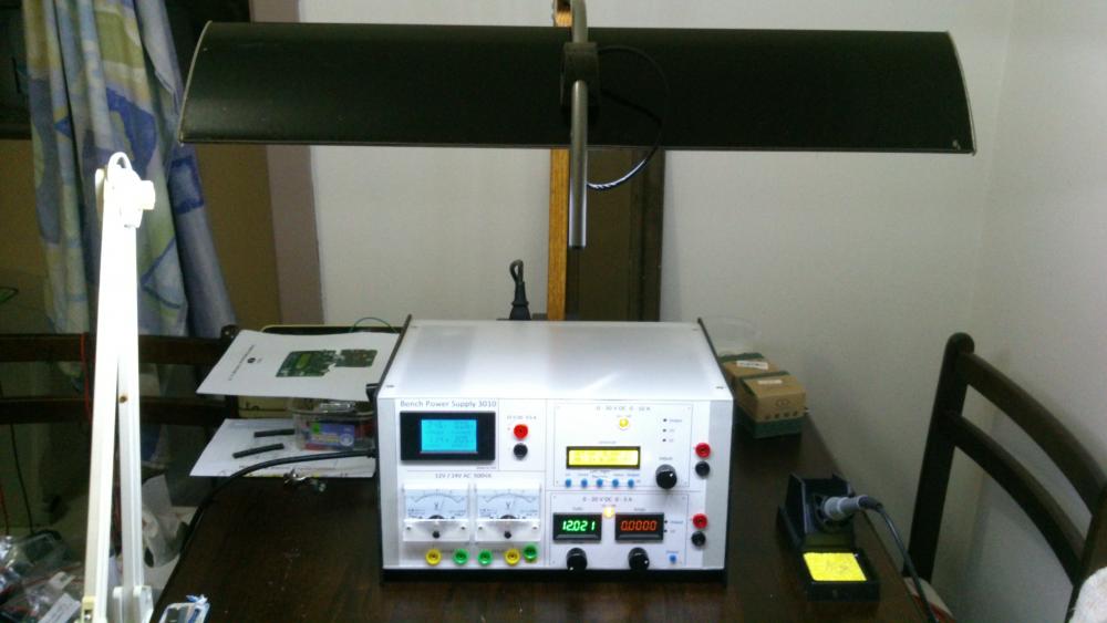
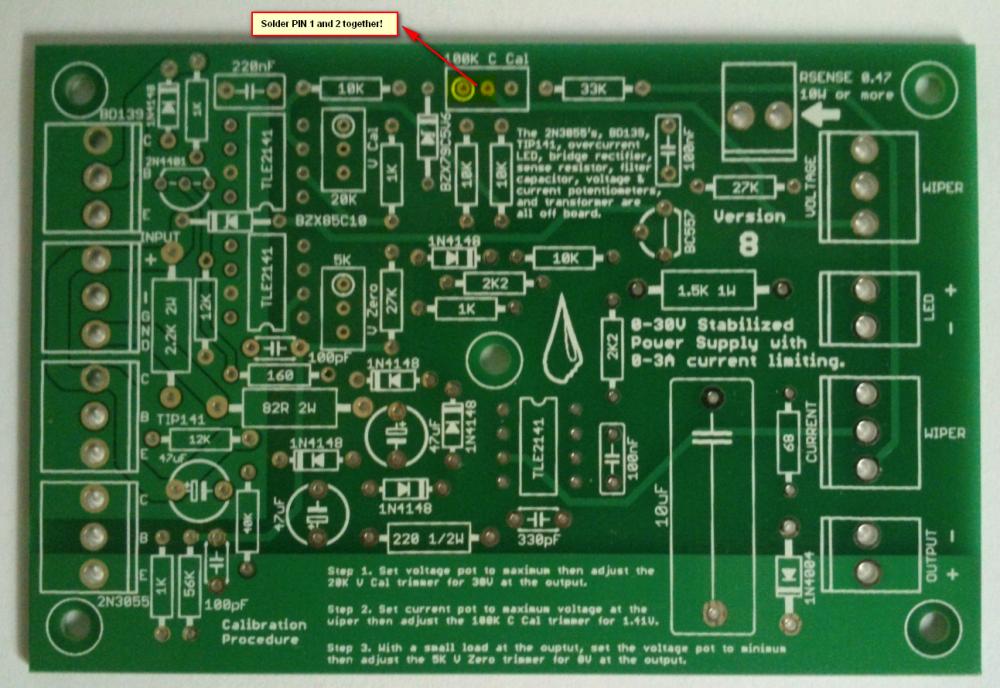
Hi all, Finally after some months have gone by, my build of the Power Supply is done. I have used liquibyte schematic Rev. 8 and had made the cirquit board according to the Gerber.zip file he posted here: 0-30V Stabilized Power Supply Page 88 posted October 6, 2014 "http://electronics-lab.com/community/index.php?/topic/29563-0-30v-stabilized-power-supply/&page=88" I left out D10 and R15 as per his description. I have plenty of boards leftover if someone has a need for it. There was only one mistake liquibyte made which have outlined in one of the pictures uploaded here. I was fortunate enough to get a big case with a Toroidal transformer from the scrapyard. Also many parts are recycled from various sources. Regards, William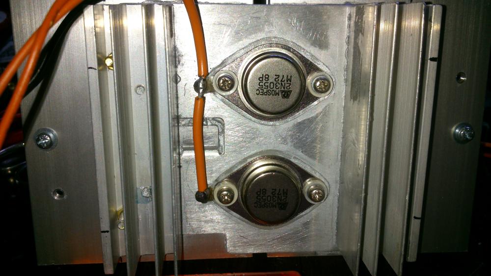

 4 points
 -
Finally, my post with the Eagle .sch and .brd, full gerbers, and parts list for Digikey in a zip file. I'm also including many of the pics I took as I was building that were posted both before and after this post. I'm still not completely done and may add more pics later. One thing I have changed is the third transformer for the auxiliary circuitry for the temperature sensor and fans and the displays (I wanted a better transformer than the Radio Shack special I had on hand). Archive attached. 30V.zip
 3 points
 -

Solar-powered Bee Hotel w/ Particle Argon (ongoing project)
Jolin He and one other reacted to JamesMVictoria for a topic
Nice one, I like it.2 points -

How to easily turn on/off all debug message on Arduino IDE
SharonWatkins and one other reacted to MrNams for a topic
But even if we disable debug, it will call print method and do not print anything. I mean we should make it something like #ifdef DEBUG Serial.print("\n debug controlled print"); #endif Here when we disable macro, its like code is not written for compiler, code will be removed in macro processing itself.2 points -

H Bridge PWM DC Motor Driver + PCB
senaka ranathunga and one other reacted to sam.moshiri for a topic
An H-Bridge (Full-Bridge) driver is quite popular in driving loads such as brushed DC motors and it is widely used in robotics and industry. The main advantages of using an H-Bridge driver are: high efficiency, rotation direction change, and braking the motor. In this article/video, I have introduced a complete H-Bridge DC motor driver using four IR3205 power MOSFETs and two IR2104 MOSFET drivers. Theoretically, the above-mentioned MOSFET can handle currents up to 80A, however, in practice we can expect to get currents up to 40A if the MOSFET temperature is kept as low as possible, using a big heatsink or even a fan. References Article: https://www.pcbway.com/blog/technology/Powerful_H_Bridge_DC_Motor_Driver.html [1]: IRF3205 Datasheet: http://www.irf.com/product-info/datasheets/data/irf3205.pdf [2]: IR2104 Datasheet: https://www.infineon.com/dgdl/Infineon-IR2104-DS-v01_00-EN.pdf?fileId=5546d462533600a4015355c7c1c31671 [3]: 1N5819 Datasheet: https://www.diodes.com/assets/Datasheets/ds23001.pdf [4]: IR2104 Schematic Symbol, PCB Footprint, 3D Model: https://componentsearchengine.com/part-view/IR2104PBF/Infineon [5]: IRF3205 Schematic Symbol, PCB Footprint, 3D Model: https://componentsearchengine.com/part-view/IRF3205ZPBF/Infineon [6]: CAD Plugins: https://www.samacsys.com/library-loader-help2 points -

Non Contact Hand Sanitizer Dispenser, Easy, Cheap, No Arduino!
sam.moshiri and one other reacted to admin for a topic
Thanks for sharing your project with us. Could you give more details on the control board?2 points -
The original circuit should work fine up to 15V at 1A if you replace the old opamps with the newer higher voltage ones. You probably should recalculate the resistors that set the maximum voltage and current outputs. If the Chinese kit uses the transistor that shorts the opamp output when the power is turned off then the resistors that feed the transistor need to be recalculated for the reduced voltage. I have used perforated stripboard for many projects including very complicated ones. The copper strips are cut to length with a drill-bit and become almost half the wiring of a pcb. The parts and a few short jumper wires become the remainder of the wiring. Only one wire is in each hole so changing a part is easy like on a pcb.2 points
-
Hi, as promised I made an English translation of my working. Maybe there is few mistakes and I am sorry for that ! Good reading. ExplicationEN.pdf2 points
-
I use copper wire, not rice wire. They put rice in everything they make, especially batteries.2 points
-

0-30 Vdc Stabilized Power Supply
electron234 and one other reacted to elctro123 for a topic
So Finally which version of schematic is correct / flawless to build the PSU ?2 points -
February 23 above on this page has the latest schematic of the revised 3A lab power supply.2 points
-
Does anyone has LM3914 pspice library? i desperately need it..pleeeeease!2 points
-

Low power solenoid?
AmelieScott and one other gave a reaction for a topic
I want to apply force for an extended amount of time (10 secs to a couple minutes) using a solenoid actuator. Unfortunately, it seems that solenoids use a lot of power when they are active. Is there a solenoid type that will only use power when switching between active and not active? There's probably a way I can do this with an external mechanism, but I was wondering if there may be commercial solenoids that have this built-in. Thanks, Jessica2 points -
Illegal content (ebook/magazines/software) will be deleted without any notice. Thanks2 points
-

Overload Protector A16 ???
joeydennis11 and one other reacted to tjolle62 for a topic
In a few circuit diagrams i have they refer to a what seems to me is a transistor with B C E as a overload protector and with number A16 and i have looked for a few hours on the net and i can't find anything on this little fellow, Anyone knows what I'm looking for and wanna share that info Please .... Come on !! 48 visits !! some one must know what it is !!! PNP is it also...........2 points -
Overload Protector A16 ???
joeydennis11 and one other reacted to tjolle62 for a topic
At last i got a theori from a totally different place and he wasn't shure either but he had a weak memory that it could be 1A16 and a PNP transistor but after several deep searches on the I-net it didn't make any kind of senses whatsoever ???2 points -

Car battery to parallel port
tracythomas50 and one other reacted to MP for a topic
When you use your resistive divider to drop the voltage down to 5 volts, you just need to select values of resistors to limit the current. This is basic ohm's law. V/R. Was this your question or did I misunderstand? I am not sure how you intend to monitor status by using one 5 volt pin. As an interface to the parallel port, you could use an LM3914. This would give you the resolution you need. There are also many other ways to proceed. You need to convert from analog to digital to read anything useful from the parallel port. MP2 points -

Car battery to parallel port
tracythomas50 and one other reacted to Omni for a topic
Hi TJBraza, http://www.analog.com/UploadedFiles/Data_Sheets/ADT7485A.pdf Although, it will probably require a small program written in C or Visual basic to convert the string MSB & LSB into a more easier read etc... Take a moment and review the data sheet, the IC has a lot of potential.2 points -

SL100 & SK100 transistor
AmelieScott and one other reacted to alanng96 for a topic
I can't find SL100 & SK100 transistor :'( Which transistors can replace these? Thank you for your help~ ;)2 points -
Calm down people. It is not Mixos's fault, if it is against the law he has to remove the content. This site is very good for asking electronic related questions, I have yet to find a better one.2 points
-

Please help to determine which silk screen is genuine
Marie P Cox reacted to HarryA for a topic
First off one can not read the text on the second IC. They claim fake ICs come in two types; those that are commercial grade and sold as military grade. And those that are used from discarded equipment. The latter type may well have the correct text on them. I gather they do not manufacture fake ICs as they are too inexpensive to be bothered with.1 point -
You can add a decoupling capacitor. Sometimes, the output waveform can be clipped due to noise in the power supply. Adding a decoupling capacitor between the power supply and the ground can help reduce the noise and improve the output waveform.1 point
-
Hall Sensor Bypass for Coffee Grinder
millicurie999 reacted to HarryA for a topic
I gather the machine has a fixed number of pulses it expects for each type of brew. It counts these via the two magnets. It also monitors the current draw by the motor. If the motor current drops off (no longer grinding) while it has not reach its count of rotations it "thinks" it is out of beans. If it is not out of beans and the motor is really working then it is missing counts at the hall effect sensor is what you are thinking? If it is really is out of beans it would discard the grounds that it has so far also? On second thought if it is missing counts it would run longer and grind to much coffee. So it must be that there are more counts to go and the current to the motor has fallen off?1 point -
MOD-23 counter
Thatswhatshesaid reacted to HarryA for a topic
The circuit below is similar to what you want to do. Using a 4 input NAND gate you can connect it to the 4 outputs that represent the valve you want. Your NAND gate output would connect to the clr line. 1 point
 -
I am working with CS5484 for a project and I am unable to configure the IC
Conor Torres reacted to HarryA for a topic
There is a library file ( GOLANG library for SPI ) here that maybe helpful? https://github.com/stamp/CS5484 I have problems finding the page that has the {code} button to download the file; you may have to dork around with the URL a bit.1 point -

Rheostat power rating
JamieOkeefe reacted to uziao for a topic
Hello friends. Very interesting topic you have here. You can model the electrodes underwater as an capacitor in parallel with a resistor (a leaky capacitor). Maybe this is why he used a bifilar coil... Bifilar coils are self resonant coils because of their capacitance. You can see this article here: https://sci-hub.st/https://doi.org/10.1002/cta.2830 The autor proposed a resonant tank circuit without the capacitor, using only the capacitance of the bifilar coil. If the electrodes underwater behave like a true capacitor, he wouldnt need 2 coils... Only one coil would do the job... Maybe the trick lies in the coils only...1 point -
Help identifying electronic components
Guy Shemesh reacted to HarryA for a topic
If you compare your board with the one on Ebay that one looks like the better board. You may gain some insight by comparing the P6? on your board with the three in the schematic and see if it connects the same as one of them. This is the schematic of the Viber12a in a battery charger.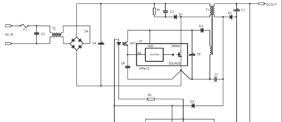
 1 point
 -
Desktop Pick and Place Machines
Zahid Gul Khan reacted to HarryA for a topic
There is information here on Visual Servoing that maybe helpful; particularly the numerous references at the end of the article. https://en.wikipedia.org/wiki/Visual_servoing If you look at a bmp file of a smd image like this one (I could not find an image of the bottom of a smd). You can see the white background as FF FF FF and one scan line across the component highlighted. So in theory one could find the four corners and calculated the rotation and any x y offset. In bmp files the image is inverted. If you only need the rotation then only part of one edge would be required to calculate it I believe. smd compoint.bmp
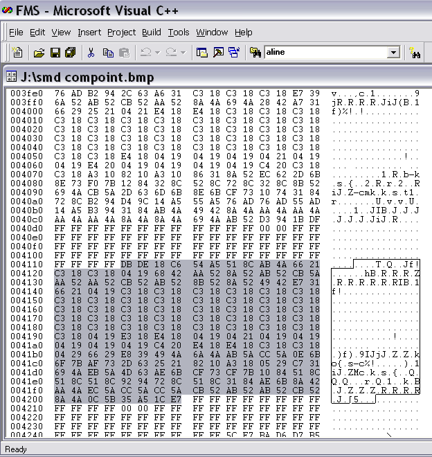 1 point
 -

Non Contact Hand Sanitizer Dispenser, Easy, Cheap, No Arduino!
sam.moshiri reacted to Sugandhan Vazhumuni for a topic
Thanks for Sharing1 point -
Power supply circuit ideas
gztoppower reacted to HarryA for a topic
If you do not need SMD perhaps "The LT138A/LT338A (LM138/LM338) series of adjustable regulators provide 5A output current over an output voltage range of 1.2V to 32V." The LM338 is about 1$ each on ebay.1 point -
One 2N3055 transistor overheats in the original circuit that used a 24VAC transformer and produces 25VDC at 3A. Therefore I used higher voltage opamps, a 28V 4.2A transformer, a more modern driver transistor Q2 that can be cooled well and two 2N3055 transistors to share the heat on a very large heatsink. Some people added a fan and a smaller heatsink instead of a huge heatsink. If you connect the two 24V windings of your transformer in series and use the centertap as 0V then its output voltage will be 24VAC x 1.414= 34V minus the 1V for the two rectifiers then the supply voltage will be too low because the circuit needs a 28VAC transformer. Your transformer voltage is too high so it cannot be used for this project. Or you could parallel the two 24VAC windings or with the centertap as above then the maximum regulated output voltage will be 25VDC at 3A.1 point
-
750W DC Motor Speed Controler 0-100% with Schematic and PCB Layout
Youkito1991 reacted to repairman2be for a topic
Hi Youkito1991, Nice work!. Thank you for sharing your design and make the PCB available for anyone who wish to use it. Your description is nice and also the support of pictures is very useful. Regards, William1 point -

acid_circuit
soldertools1 reacted to audioguru for a topic
Why are you using an old fashioned vented lead-acid battery? Most circuits today are powered by rechargeable Ni-MH or Lithium batteries that have no acid.1 point -
Septic Service Oologah - Every A Septic Solutions employee receives continuing education on all types of septic systems to stay current on the latest technologies and products for your specific system.1 point
-

MS.NET on ARM devices
JerryAcert reacted to Dmitry for a topic
Some developers really need MS .NET Framework for some reason on their ARM devices (mainly on Raspberry Pi). So, basing on their requests, I have made a short tutorial on how to setup .NET on Raspberry Pi.1 point -
WellPCB http://www.wellpcb.com WELLPCB is focusing on online prototypes orders, to meet the requirement of Low cost, Fast delivery, Easy order for customers around the world.
 1 point
 -

PCB manufactureres
Soldertraining reacted to youth for a topic
I use WellPCB quite a bit. They aren't the cheapest, but the quality is superb, they may offer features and service you might need. http://www.wellpcb.com/ If it's only a single board or two I tend to make them myself. 1 point
 -
Ok, skip the voltage and current LCD panel With R18 = 33 kOhm I have got 4,7 A on out... U3 was replaced for another .1 point
-
You ask for a lot! Start with Ebay.com for transmitters and receivers: see: http://www.ebay.com/itm/Mini-88-108MHz-FM-Transmitter-Module-Wireless-Microphone-Dictagraph-Interceptor/141659602950?_trksid=p2047675.c100005.m1851&_trkparms=aid%3D222007%26algo%3DSIC.MBE%26ao%3D2%26asc%3D40832%26meid%3D5caec1e4bbe74e2fa065b6379434198a%26pid%3D100005%26rk%3D2%26rkt%3D6%26sd%3D1116497410721 point
-
You points are well made; thanks. On day one I found two voltage boosters on Ebay that gave more than 100 volts so I ordered both of them from China. The first one I received was a 12v dc to 200 v dc. After connecting it up and adjusting it for 200 v I put a 100k resistor across the output and got 2 volts output! It took a one mega-ohm load to keep 200 v. The second one (12v dc to 220 v ac) works well. I connected it to the 220v to 120v step down transformer and into a full wave bridge rectifier with a 100mfd capacitor and got 140 v dc; 9.6 volts input. With a 8.4 v NiMH rechargeable battery I get 128 v dc. So I am happy with that and very surprised that the 50/60 hertz transformer works at all!1 point
-

ARMA IoT-wifi shield for Arduino
JolynObjecy reacted to vishwas95 for a topic
Are u looking for a way to connect the Arduino to the internet easily? Do you want to develop your IoT project quickly without much hassle? ARMA IoT might just be the thing for you! The simple and efficient Arduino shield is powered through a esp12f wifi module, which enables it to be connected to the wifi network. it also has an SD card slot for for extra data storage like its wired brethren the Ethernet Shield. The ARMA IoT goes a step further and provides an easy plug and play feature for most of the common devices such as sensors, motors, LCDs and relays. The ARMA IoT is a great place for beginners to start their IoT project, as it requires minimum time to setup the hardware all thanks to the plug and play feature. Even the programming is simplified through the help of apps such as Blynk, which provides easy feature of controlling the Arduino through your Android or iOS phone. Thingspeak an upcoming IoT platform is also supported by the shield. The ARMA IoT platform proves as a tool for aspiring beginners and also a prototyping tool for advanced users. IoT products can be developed much faster with the help of this board. Weather it is creating a simple IoT project such as blinking LEDs or controlling relays, or developing your own Home automation system, the ARMA IoT facilitates it all and things seem to happen rather quickly with all the features provided on the board. The wifi connection feature can provide fast communication between devices or two instances of ARMA itself, making it applicable for simple swarm robotics, wireless controllers etc. The applications can also be extended to simple robotics, Energy management systems and it does not stop there as it all depends upon the users creativity. To get started simple tutorials are provided on the YouTube page of ARMA IoT, the link below guides on the setup of Arduino and ARMA IoT with the help of Blynk app More tutorials and projects will be posted to help you make the most of the shield. Of Course there are also various DIY communities that can provide you with both support and inspiration for your upcoming IoT projects. thus ARMA is another simple board that has the ability to bind many devices together. The ARMA IoT is still undergoing a crowdfunding campaign in Indiegogo and is available for pre-order. https://www.indiegogo.com/projects/arma-iot-breakout-board-for-arduino#/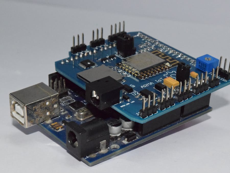
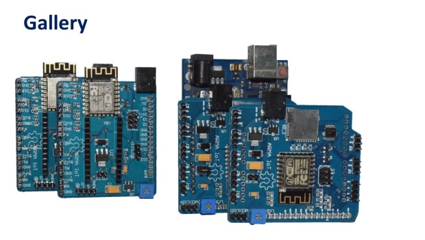
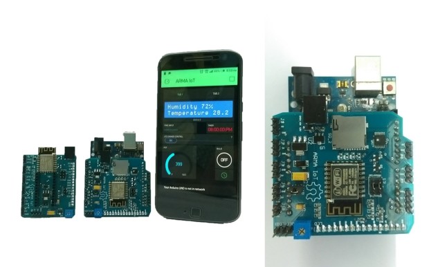 1 point
 -
You need to be more specific about your project, so we can help.1 point
-

Sensor alarm and transmitter
Jacquelyn Norris reacted to steve10101 for a topic
Hiya, I now cant find the projects I found yesterday sorry... but the below link is a device similar to what I'm looking for, but I'm looking to make this work in reverse (hoping this may help). The distance I'm trying to achieve would be for the alarm to activate if transmitter was anything from 0-10 feet away. http://www.pimall.com/nais/rdiftagalert.html1 point -
Distortion can blow out a tweeter because distortion has strong high frequency harmonics. Try feeding an input directly to the power amplifier without connecting the preamp.1 point
-
The output of a preamp will produce clipping distortion if the input level is too high. The pickup from an electric guitar produces a level much higher than an FM tuner, a CD player or an MP3 player. Most preamps for a guitar pickup use a Jfet because of its very high input impedance with a gain of only about 1.4 times.1 point
-
The same basic blocking oscillator circuit, normally used to drive a flyback transformer, can also drive a centre tapped or dual primary mains transformer. Here's an example of a capacitor charger using a mains transformer with a centre tapped primary. It should be able to drive a voltage multiplier circuit. C1 1 uF D2 1N4948 R2 +------||------+ T1 1.2kV PRV 1K 1W | | +-----|>|-----/\/\---+------o + | R1 4.7K, 1W | red ||( blk | +-----/\/\-----+------+ ||( | | yel )||( +_|_ C2 + o----------------------------------+ ||( --- 300 uF | red )||( - | 450 V | +--------------+ ||( | | Q1 | ||( blk | 6 to 12 | |/ C +--------------------+------o - VDC, 2A +----| 2N3055 Stancor P-6134 D1 _|_ |\ E 117 V Primary (blk-blk) 1N4007 /_\ | 6.3 VCT Secondary (red-yel-red) | | - o------------+------+ http://www.repairfaq.org/sam/samschem.htm#schssi1 point
-

An excellent electronics manual
Jordan&tiffany reacted to grsparks for a topic
After running across this at the public library in town, I just had to order my own copy: "Practical Electronics for Inventors" by Paul Scherz It covers just about everything from DC to Microcontrollers and is well illustrated.1 point -
0-30 Vdc Stabilized Power Supply
winterpigz reacted to audioguru for a topic
Hi Gruber, The current-setting pot in this project has a tolerance of 20% and the values of the resistors were chosen so it provides 3A if the pot's resistance is 20% high. If your pot's resistance is 20% low then with it set to max, the project will try to produce 4.2A. Such a high current will overload the transformer and cause its core to saturate. A transformer with a saturated core isn't a transformer anymore, it is a piece of wire across the mains, blowing fuses. You should add a trimpot in series with the current-setting pot. Adjust the trimpot so the project supplies a max of exactly 3A when the current-setting pot is at max.1 point -

looking for data on LINE IN of soundcards
concepcionua3 reacted to Yogi for a topic
;D thank1 point -

0-30 Vdc Stabilized Power Supply
HaddyS reacted to juanpmoron for a topic
R16 is 1K and is OK ???1 point