Leaderboard
Popular Content
Showing content with the highest reputation since 07/27/2015 in all areas
-

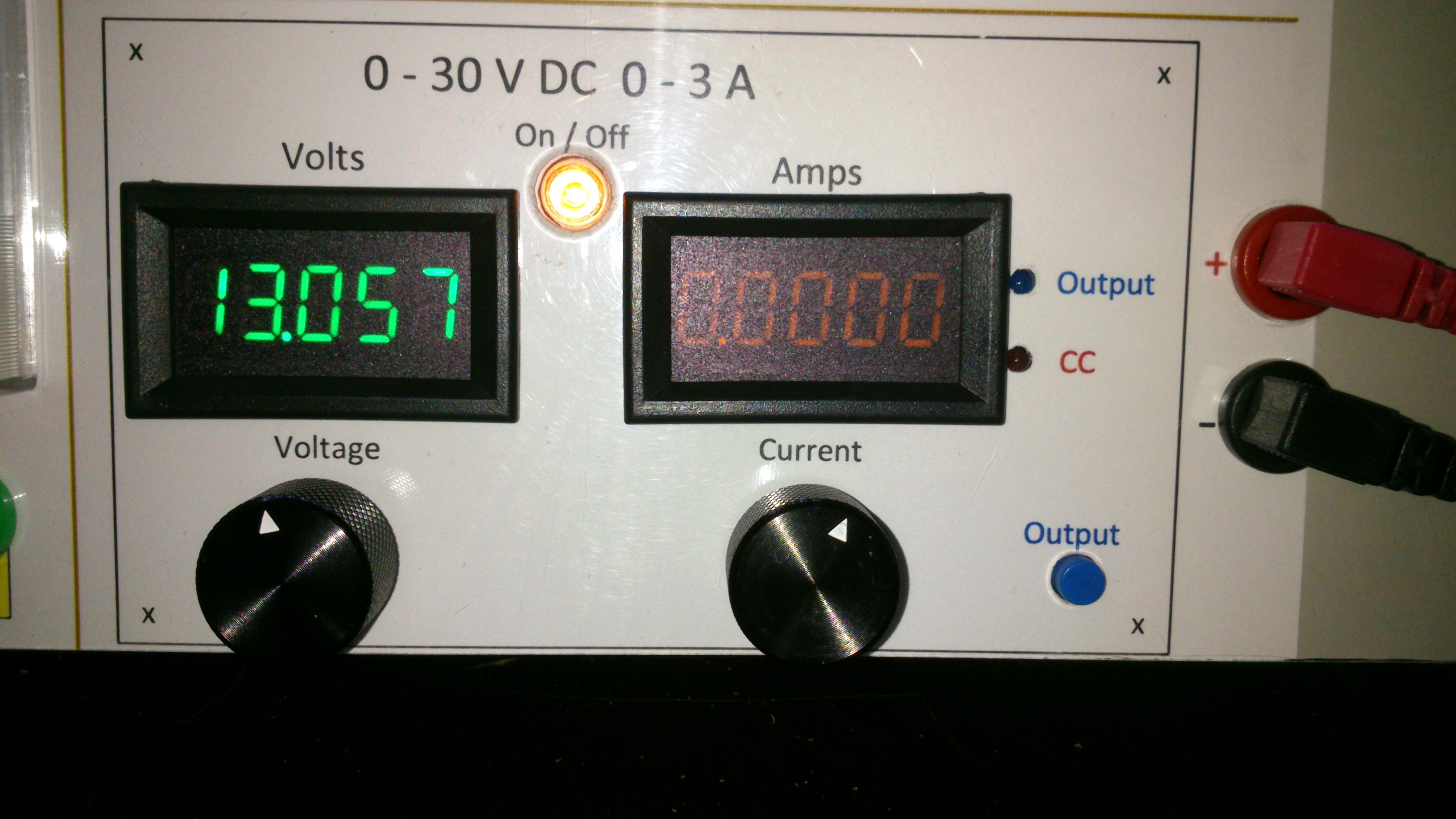
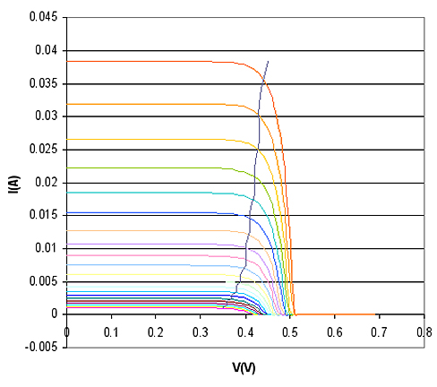
0-30V 0-3A Latest Data
AsSa and 3 others reacted to repairman2be for a topic
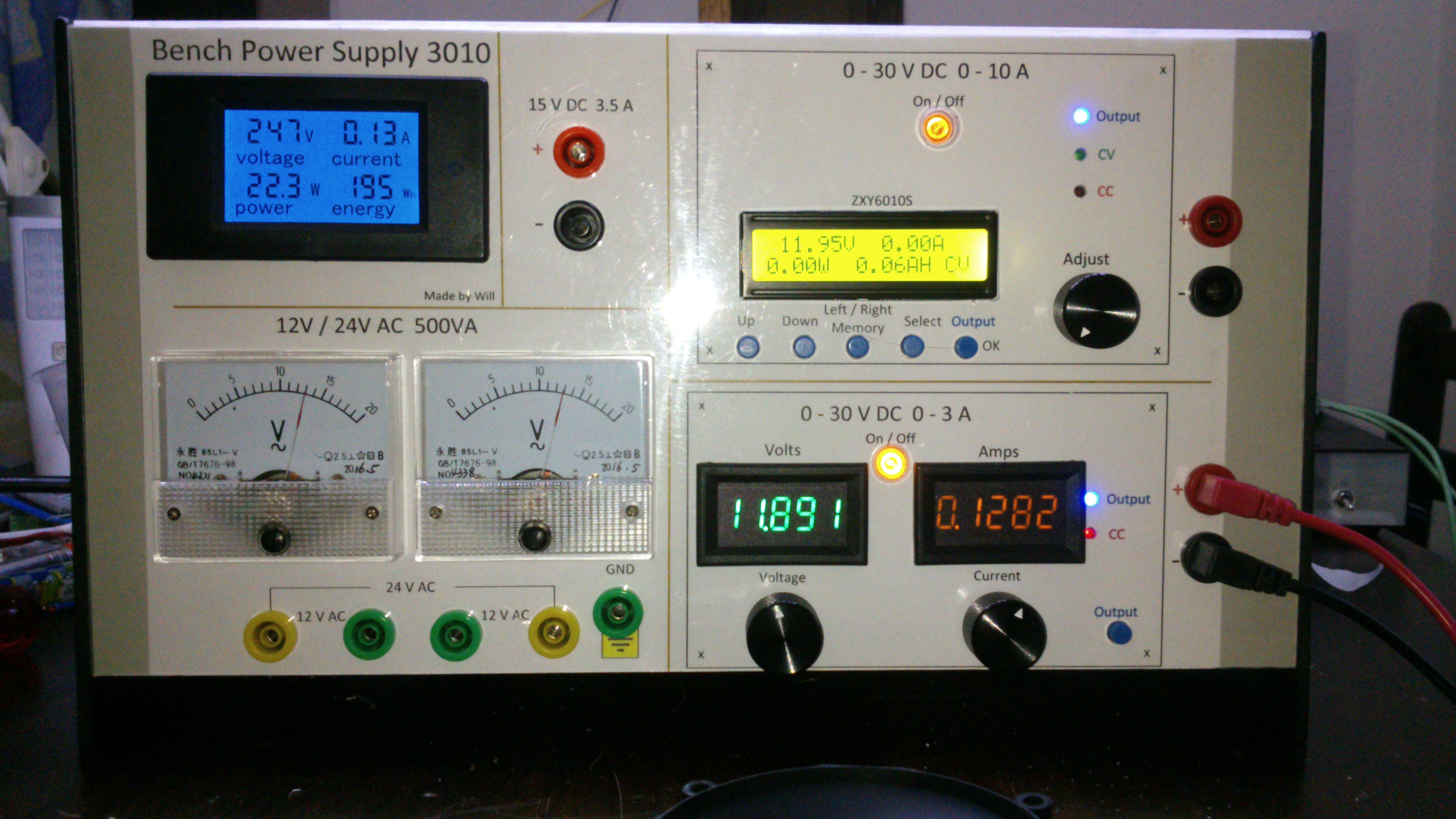
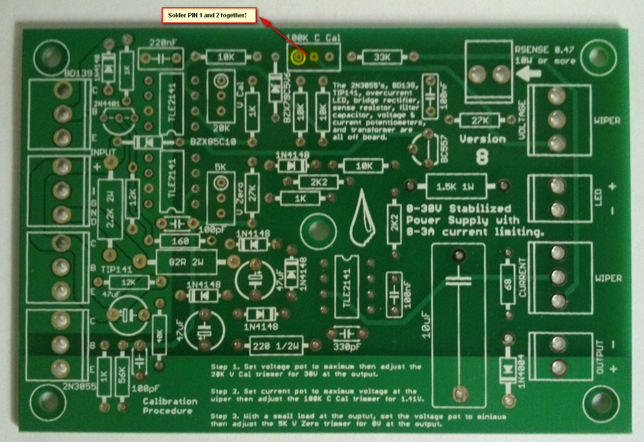
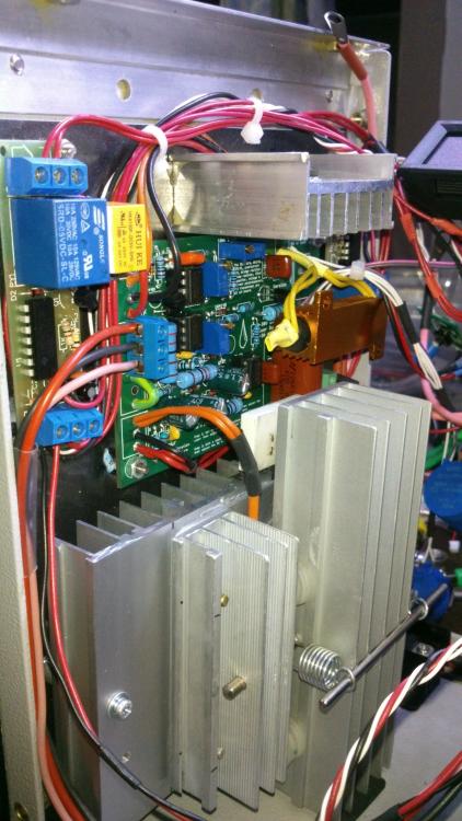
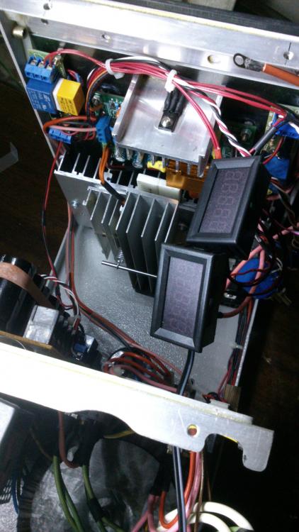
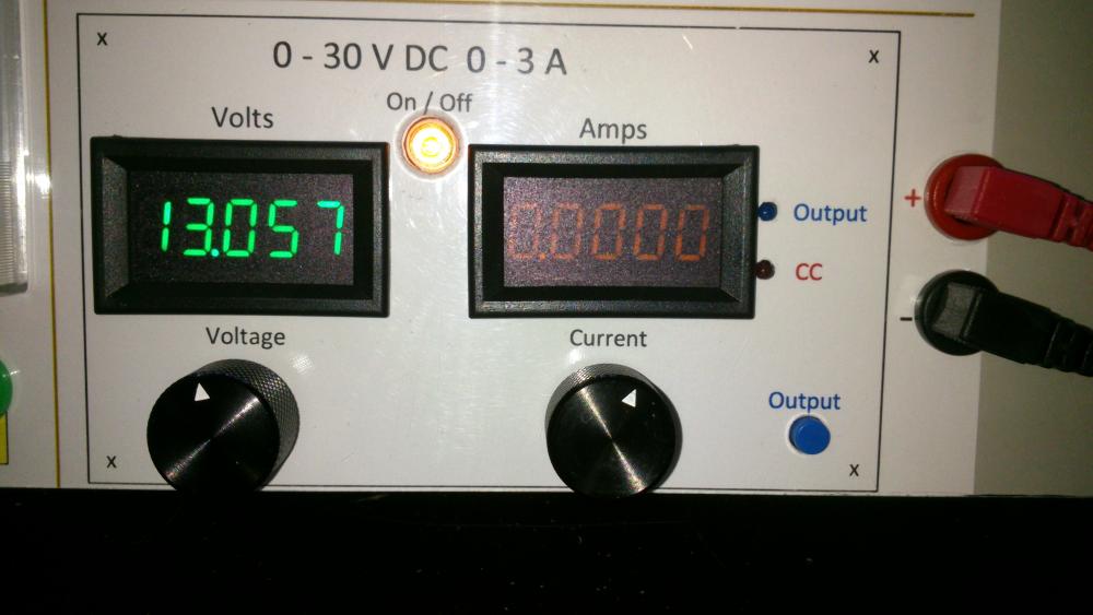
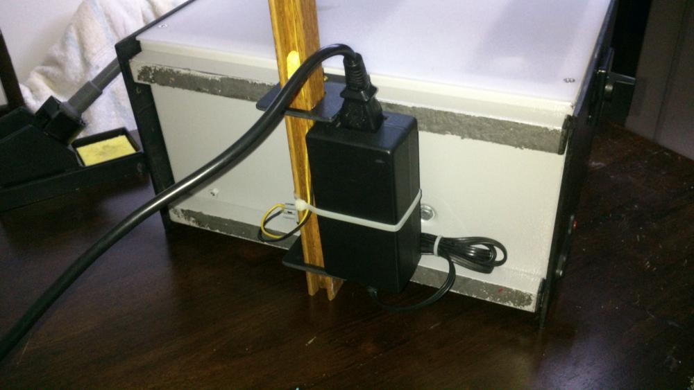
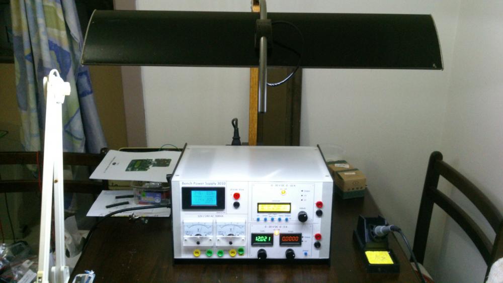
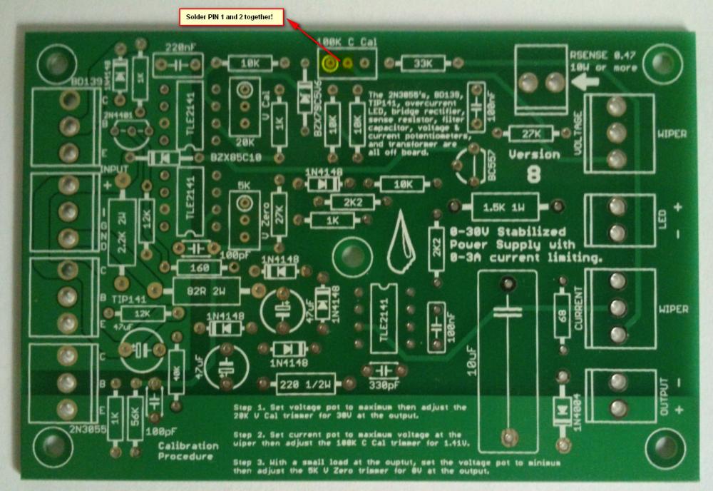
Hi all, Finally after some months have gone by, my build of the Power Supply is done. I have used liquibyte schematic Rev. 8 and had made the cirquit board according to the Gerber.zip file he posted here: 0-30V Stabilized Power Supply Page 88 posted October 6, 2014 "http://electronics-lab.com/community/index.php?/topic/29563-0-30v-stabilized-power-supply/&page=88" I left out D10 and R15 as per his description. I have plenty of boards leftover if someone has a need for it. There was only one mistake liquibyte made which have outlined in one of the pictures uploaded here. I was fortunate enough to get a big case with a Toroidal transformer from the scrapyard. Also many parts are recycled from various sources. Regards, William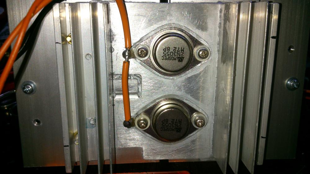

 4 points
 -
Finally, my post with the Eagle .sch and .brd, full gerbers, and parts list for Digikey in a zip file. I'm also including many of the pics I took as I was building that were posted both before and after this post. I'm still not completely done and may add more pics later. One thing I have changed is the third transformer for the auxiliary circuitry for the temperature sensor and fans and the displays (I wanted a better transformer than the Radio Shack special I had on hand). Archive attached. 30V.zip
 3 points
 -

Solar-powered Bee Hotel w/ Particle Argon (ongoing project)
Jolin He and one other reacted to JamesMVictoria for a topic
Nice one, I like it.2 points -

How to easily turn on/off all debug message on Arduino IDE
SharonWatkins and one other reacted to MrNams for a topic
But even if we disable debug, it will call print method and do not print anything. I mean we should make it something like #ifdef DEBUG Serial.print("\n debug controlled print"); #endif Here when we disable macro, its like code is not written for compiler, code will be removed in macro processing itself.2 points -

H Bridge PWM DC Motor Driver + PCB
senaka ranathunga and one other reacted to sam.moshiri for a topic
An H-Bridge (Full-Bridge) driver is quite popular in driving loads such as brushed DC motors and it is widely used in robotics and industry. The main advantages of using an H-Bridge driver are: high efficiency, rotation direction change, and braking the motor. In this article/video, I have introduced a complete H-Bridge DC motor driver using four IR3205 power MOSFETs and two IR2104 MOSFET drivers. Theoretically, the above-mentioned MOSFET can handle currents up to 80A, however, in practice we can expect to get currents up to 40A if the MOSFET temperature is kept as low as possible, using a big heatsink or even a fan. References Article: https://www.pcbway.com/blog/technology/Powerful_H_Bridge_DC_Motor_Driver.html [1]: IRF3205 Datasheet: http://www.irf.com/product-info/datasheets/data/irf3205.pdf [2]: IR2104 Datasheet: https://www.infineon.com/dgdl/Infineon-IR2104-DS-v01_00-EN.pdf?fileId=5546d462533600a4015355c7c1c31671 [3]: 1N5819 Datasheet: https://www.diodes.com/assets/Datasheets/ds23001.pdf [4]: IR2104 Schematic Symbol, PCB Footprint, 3D Model: https://componentsearchengine.com/part-view/IR2104PBF/Infineon [5]: IRF3205 Schematic Symbol, PCB Footprint, 3D Model: https://componentsearchengine.com/part-view/IRF3205ZPBF/Infineon [6]: CAD Plugins: https://www.samacsys.com/library-loader-help2 points -

Non Contact Hand Sanitizer Dispenser, Easy, Cheap, No Arduino!
sam.moshiri and one other reacted to admin for a topic
Thanks for sharing your project with us. Could you give more details on the control board?2 points -
The original circuit should work fine up to 15V at 1A if you replace the old opamps with the newer higher voltage ones. You probably should recalculate the resistors that set the maximum voltage and current outputs. If the Chinese kit uses the transistor that shorts the opamp output when the power is turned off then the resistors that feed the transistor need to be recalculated for the reduced voltage. I have used perforated stripboard for many projects including very complicated ones. The copper strips are cut to length with a drill-bit and become almost half the wiring of a pcb. The parts and a few short jumper wires become the remainder of the wiring. Only one wire is in each hole so changing a part is easy like on a pcb.2 points
-
Hi, as promised I made an English translation of my working. Maybe there is few mistakes and I am sorry for that ! Good reading. ExplicationEN.pdf2 points
-
I use copper wire, not rice wire. They put rice in everything they make, especially batteries.2 points
-

0-30 Vdc Stabilized Power Supply
electron234 and one other reacted to elctro123 for a topic
So Finally which version of schematic is correct / flawless to build the PSU ?2 points -
February 23 above on this page has the latest schematic of the revised 3A lab power supply.2 points
-
Does anyone has LM3914 pspice library? i desperately need it..pleeeeease!2 points
-

Low power solenoid?
AmelieScott and one other gave a reaction for a topic
I want to apply force for an extended amount of time (10 secs to a couple minutes) using a solenoid actuator. Unfortunately, it seems that solenoids use a lot of power when they are active. Is there a solenoid type that will only use power when switching between active and not active? There's probably a way I can do this with an external mechanism, but I was wondering if there may be commercial solenoids that have this built-in. Thanks, Jessica2 points -
Illegal content (ebook/magazines/software) will be deleted without any notice. Thanks2 points
-

Overload Protector A16 ???
joeydennis11 and one other reacted to tjolle62 for a topic
In a few circuit diagrams i have they refer to a what seems to me is a transistor with B C E as a overload protector and with number A16 and i have looked for a few hours on the net and i can't find anything on this little fellow, Anyone knows what I'm looking for and wanna share that info Please .... Come on !! 48 visits !! some one must know what it is !!! PNP is it also...........2 points -
Overload Protector A16 ???
joeydennis11 and one other reacted to tjolle62 for a topic
At last i got a theori from a totally different place and he wasn't shure either but he had a weak memory that it could be 1A16 and a PNP transistor but after several deep searches on the I-net it didn't make any kind of senses whatsoever ???2 points -

Car battery to parallel port
tracythomas50 and one other reacted to MP for a topic
When you use your resistive divider to drop the voltage down to 5 volts, you just need to select values of resistors to limit the current. This is basic ohm's law. V/R. Was this your question or did I misunderstand? I am not sure how you intend to monitor status by using one 5 volt pin. As an interface to the parallel port, you could use an LM3914. This would give you the resolution you need. There are also many other ways to proceed. You need to convert from analog to digital to read anything useful from the parallel port. MP2 points -

Car battery to parallel port
tracythomas50 and one other reacted to Omni for a topic
Hi TJBraza, http://www.analog.com/UploadedFiles/Data_Sheets/ADT7485A.pdf Although, it will probably require a small program written in C or Visual basic to convert the string MSB & LSB into a more easier read etc... Take a moment and review the data sheet, the IC has a lot of potential.2 points -

SL100 & SK100 transistor
AmelieScott and one other reacted to alanng96 for a topic
I can't find SL100 & SK100 transistor :'( Which transistors can replace these? Thank you for your help~ ;)2 points -
Calm down people. It is not Mixos's fault, if it is against the law he has to remove the content. This site is very good for asking electronic related questions, I have yet to find a better one.2 points
-

Integrating DHT11 with Beetle ESP32 C3 and Home Assistant
JamesMVictoria reacted to CETECH for a topic
This project will allow you to monitor environmental conditions in your home automation setup. Here are the steps to achieve this: Integrating DHT11 with Beetle ESP32 C3 and Home Assistant 1. Components Required Before we begin, gather the necessary components: BeetleESP32C3 development board DHT11 temperature and humidity sensor Jumper wires USB cable for programming A computer with the Arduino IDE or ESPHome installed Get PCBs for Your Projects Manufactured You must check out PCBWAY for ordering PCBs online for cheap! You get 10 good-quality PCBs manufactured and shipped to your doorstep for cheap. You will also get a discount on shipping on your first order. Upload your Gerber files onto PCBWAY to get them manufactured with good quality and quick turnaround time. PCBWay now could provide a complete product solution, from design to enclosure production. Check out their online Gerber viewer function. With reward points, you can get free stuff from their gift shop. Also, check out this useful blog on PCBWay Plugin for KiCad from here. Using this plugin, you can directly order PCBs in just one click after completing your design in KiCad. 2. Flashing ESPHome to Beetle ESP32 C3 Install ESPHome on your computer. You can follow the instructions in my previous blog. Create an ESPHome configuration file (e.g., dht11.yaml) with the following content: sensor: - platform: dht pin: 0 model: dht11 temperature: name: "Living Room Temperature" humidity: name: "Living Room Humidity" update_interval: 5 s Replace placeholders (YourWiFiSSID, YourWiFiPassword, etc.) with your actual values. Compile and upload the configuration to your Beetle ESP32 C3 using the ESPHome CLI. 3. Integrating with Home Assistant Open Home Assistant. Click on Configuration (bottom left) and go to Integrations. Click the + button and select ESPHome. Enter the IP address of your ESP32 (leave the port as 6053) and click Finish. 4. Viewing Temperature and Humidity Once integrated, Home Assistant will discover the Beetle ESP32 C3 module and create entities for temperature and humidity. You can access these entities in Home Assistant’s dashboard and display them as cards or graphs. And that’s it! You’ve successfully integrated the DHT11 sensor with your Beetle ESP32 C3 and Home Assistant. Feel free to customize and expand this project based on your needs. Happy monitoring! 🌡️💧🏠1 point -

We had an idea and its now a helpful product: ProBUDDY Kits
Jacquelyn Norris reacted to sundayrobotics for a topic
Breadboards, arduinos, cables.. We all love and work with those but when they are connected together as the hardware of our projects, it can get messy. To help all of us at that point, we've created a solution, first we used it, then sent prototypes out for review and then its now live on Kickstarter waiting for you to reserve yours: ProBUDDY Kits. Here is how it works: The hardware is taken on to our Base Plates and get fixed with special magnetic holders called ProBUDDY's. Then its so easy to work on, carry, store, demonstrate your projects. You can retrieve the components easily for another project. You can store your projects on any vertical (yes!) surfaces and keep your desks clean. And there are more. Here I want to share the Kickstarter link, thank you all for your support; https://www.kickstarter.com/project...y-kits-build-carry-store-your-projects-easily Best Sunday Robotics Team1 point -

Good book for beginners?
tommyhanks2 reacted to ernander123 for a topic
what else is there?1 point -

TensorFlow Lite - Magic Wand on RTL8722DM
Fahad Ibrahim reacted to Yahui Ji for a topic
Materials • Ameba D [RTL8722 CSM/DM] x 1 • Adafruit LSM9DS1 accelerometer • LED x 2 Example Procedure Connect the accelerometer and LEDs to the RTL8722 board following the diagram. Download the Ameba customized version of TensorFlow Lite for Microcontrollers library at ambiot/ambd_arduino. Follow the instructions at Arduino - Libraries to install it. Ensure that the patch files found at ambiot/ambd_arduino are also installed. In the Arduino IDE library manager, install the Arduino_LSM9DS1 library. This example has been tested with version 1.1.0 of the LSM9DS1 library. Open the example, “Files” -> “Examples” -> “TensorFlowLite_Ameba” -> “magic_wand”. Upload the code and press the reset button on Ameba once the upload is finished. Holding the accelerometer steady, with the positive x-axis pointing to the right and the positive z-axis pointing upwards, move it following the shapes as shown, moving it in a smooth motion over 1 to 2 seconds, avoiding any sharp movements. If the movement is recognised by the Tensorflow Lite model, you should see the same shape output to the Arduino serial monitor. Different LEDs will light up corresponding to different recognized gestures. Note that the wing shape is easy to achieve, while the slope and ring shapes tend to be harder to get right. Find out more at: https://www.amebaiot.com/en/amebad-micropython-periodical-timer/ Join in the community discussions at: https://www.facebook.com/groups/amebaioten https://forum.amebaiot.com/ Purchase links for the various Realtek development boards can be found at: https://www.amebaiot.com/en/where-to-buy-link/1 point -

Help identifying electronic components
Guy Shemesh reacted to GMJim for a topic
Thank you everyone for your help and advice. I found a brand new updated AMP plate (DSW Pro 550) for $150.00. I think I might just keep this one (DSW Pro 500) for parts. Thanks again!1 point -
There is an article "Design Project2 - BCD Calculator" that maybe helpful. http://homepages.cae.wisc.edu/~ece352/fall02/old_project/p2.pdf1 point
-
Non Contact Hand Sanitizer Dispenser, Easy, Cheap, No Arduino!
Sugandhan Vazhumuni reacted to sam.moshiri for a topic
You're welcome. it doesn't have a controller. the intention was to find the easiest and cheapest solution. Please follow the video and provided resources.1 point -
I am attaching a Troubleshooting FAQ’s I found for this power supply. It summarizes the 150 pages of an old thread into a single document. Hope this helps get some questions answered. 0-30V 0-3A Bench Power Supply Unit Troubleshooting FAQ’s.pdf1 point
-
This is a question always been asked so I try to make this list to cover as many pcb manufacturers as I can. This is a listing of websites making PCBs and also may including PCBAs. I will try to update the infomation now and then. http://www.pcbway.com/ -$5!!! http://www.pcbgeek.com/ http://www.sfcircuits.com http://expresspcb.com/ http://www.apcircuits.com/ http://www.10pcb.com/ http://www.goldphoenixpcb.com/ http://batchpcb.com/index.php/Products http://www.pad2pad.com/index.html http://www.pcbcart.com./ http://www.4pcb.com/ http://www.pcbfinpo.com/ http://www.sunstone.com/ http://www.pmsnewzealand.com/ http://www.ezpcb.com/ezpcbweb3/index.php http://dorkbotpdx.org/wiki/pcb_order http://pcbconnect.com/index.html http://www.screamingcircuits.com/Order/ http://www.pcborder.com/site_new/default.asp http://www.custompcb.com/ http://www.multi-circuit-boards.eu/?gclid=CK20v5fFga4CFYZN3godg1in6Q http://iteadstudio.com/store/index.php?cPath=19_20 https://www.itead.cc/open-pcb/pcb-prototyping.html http://www.seeedstudio.com/depot/fusion-pcb-service-p-835.html?cPath=185 http://imall.iteadstudio.com/open-pcb/pcb-prototyping.html?p=2&price=-100 - $0.2 !!! https://ecommerce.pcbfabexpress.com/ http://www.goldphoenixpcb.com/ http://oshpark.com https://www.protoexpress.com/ - SierraCircuits http://www.4pcbassembly.com/ http://www.mitchelectronics.co.uk/ http://www.customcircuitboards.com/ http://dirtypcbs.com/ http://www.elecrow.com/special-offer-for-2-layer-1010cm-max-green-pcb-510pcs-p-761.html http://pcbshopper.com/ http://smart-prototyping.com/PCB-Prototyping.html http://www.technotronix.us/ http://www.pcbunlimited.com/ http://store3.sure-electronics.com/ The list is not in any priority. I've never ordered board from any houses. I've just made board with the first two entries. This is a "work in progress". New board houses may be added, along with some comments.1 point
-

Rc car
Youssef_Hany1 reacted to HarryA for a topic
Perhaps the chip is over heating with to much current draw? Try connecting only two motors to see what happens. For the l298n chip itself: For the IO Peak Output Current (each Channel) – Non Repetitive (t = 100ms) 3.0A –Repetitive (80% on –20% off; ton = 10ms) 2.5A –DC Operation 2.0A TOTAL DC CURRENT UP TO 4 A1 point -

PCBGOGO after-sale service review
dorrismillerrr123 reacted to KrisDong for a topic
The board is made very precisely, it's clean and very pleasant to touch. Markings on the silkscreen layer are very good readable. Soldering does not cause trouble, tin adheres very well to soldering points with a small amount of flux. It is also worth mentioning that the PCB is very robust to desoldering. The company is very solid, although you order 10 pieces, you get at least 1 PCB more for test, prototype, present, etc. When I signed up for an account, I also got a $20 coupon for free. Excellent construction and assembly work done by PCBgogo.No problems encountered, highly recommended.1 point -
The TIP31 is 83 times slower than the BD139 that I recommend that has almost the same speed as the original 2N2219 that got too hot as Q2. Then the TIP31 will probably cause oscillation.1 point
-
The original defective circuit had many overloaded parts that will blow up. The improved version fixes it. Opamp U3 senses the output current in R7 and reduces the output voltage and output current to match the current set with P2. The maximum output current is 3.0A in the improved circuit and the two output transistors have a total maximum current rating of 30A so they will not blow up with only 3.0A.1 point
-

555 dc motor controller
FranceRouze reacted to stathis81 for a topic
Good evening to everyone. Is it ok to use TIP 120 instead of TIP 122? Thanks in advance1 point -
Since it was years ago I do not remember which page of which thread has version 6 or 7. I have the schematic and parts list of version 6 here:
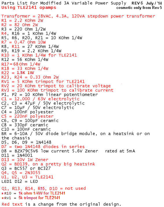
 1 point
 -

clipping circuit
soldertools1 reacted to Soldertraining for a topic
The clipping circuit does not have energy storage elements like capacitors but it includes both resistors and transistors. This circuit is normally used for the selection in the transmission purpose. The ability of diodes to allow the flow of current in only one direction. A diode is best tested by measuring the voltage drop across the diode when it is forward-biased. A forward-biased diode acts as a closed switch, permitting current to flow. No voltage exists at the diode but voltage may be present in the circuit due to charged capacitors.1 point -
high value blue color capacitor
hugomulls reacted to Soldertraining for a topic
The colors of capacitors describe the types of capacitors. The color used to identify the components or parts on the circuit board. The round blue colored balls with dots indicate that its a capacitor. Same as other colors are used for other components.1 point -

c828 transistor
joeydennis11 reacted to eplanet for a topic
hi friend i have audio amplifier made with 2 * C828. can you tell me which transistor use instead c828? thanks1 point -

555 dc motor controller
FranceRouze reacted to Hero999 for a topic
A schematic would help us to answer the question. I wouldn't recommend either. A MOSFET would probably be better.1 point -
Maybe you can consider casting soft plastic or silicon, i think this would be ideal.1 point
-

Power conversion
Cory D reacted to Bob Wettermann for a topic
"A solar charging system is not complete without an appropriate charge controller. Most units include a charge controller to charge 12-volt lead acid batteries and inverter for drawing power. Charge controllers are also available for lithium-ion to charge 10.8V packs (3 sells in series)."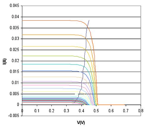 1 point
 -
How about providing a circuit. One picture is worth a thousand words!1 point
-
The current rating is not a problem. It's better to go higher than lower. Using a power relay to switch low current signals is only a problem at very low voltages. The problem with using a lower voltage relay is the contacts can arc over and what's worse it it could be unpredictable.The relay may seem fine most of the time but it could suddenly arc over due to ambient ionising radiation.1 point
-

high voltage electric arc
HaddyS reacted to ren_zokuken01 for a topic
i need to create voltaic sparks that jumps from one electrode to another between a medium of air. sort of like jacob's ladder. the distance of one electrode to another is about 0.5". i gather that the breakdown voltage of air for said distance is about 4kV. i'm targeting more of around 20-30kV, just to be sure. the sparks do not have to last long, just about 1 sec, max. the purpose of this simple contraption? i want to create a sustained jacob's ladder, rather than one lasting only a second (as the described contraption does). so what this contraption will do is apply the breakdown voltage, ionizing the air and then the sustained high voltage will be supplied by my DC arc welder that outputs 25V @ 50A. don't worry, i won't put the two to be electrically parallel to each other. the contraption has to be very cheap (would simply winding a step-up transformer be enough)?? i've tried different sources, the cheapest i found was simply buying a cheap stun gun (around $10-20) than can supply a few million volts -- pretty good. but the laws in canada does not allow the trade of any sort of weapon (even for self defense) whatsoever. i've tried looking at neon sign transformers but they cost at least $50.1 point -

DATASHEET OF SE336 (SMD IC)
PhillipGok reacted to hotwaterwizard for a topic
TOYOTA Car indicator flasher part number TOYOTA:81980-50030.1 point -
Transistors are all different. There are good ones and there are poor ones. The worst (but still passing) 2N3055 transistor has a collector to emitter leakage current of 0.7mA but a good one has much less. The collector-base leakage current is much less (a maximum of only 3.5uA at 25 degrees C) then it is amplified maybe 200 times by the current gain of the transistor so the 1k resistor from base to emitter completely kills the leakage current. R16 in our project is the "R" for the output transistors so they do not have leakage current. If R16 is missing then the output transistors will amplify their collector-base leakage current which will cause them to turn on.1 point
-
Re: high voltage meter problem
JerryAcert reacted to Hero999 for a topic
The meter will have an impedance of 10M so to divide by 10, all you need to do is connect a 90M high voltage resistor in series with it. This can be made using nine 10M resistors in series, each resistor needs to be rated to 1/10th of voltage being measured.1 point -

Electronic Gun !!!!!!!!!
Jordan&tiffany reacted to audioguru for a topic
Hi Shantanu, Electrolytic capacitors have a vent on top to slowly release gasses that build up when the capacitor is connected with backwards polarity then has a high current. With a very high current, the vent cannot release the gasses slowly so the capacitor explodes. A 9V battery cannot provide a very high current. Maybe a battery made with series-connected AA Ni-Cad or Ni-MH cells would provide enough current for a backwards electrolytic capacitor to explode. Bad-smelling "fluff" comes out.1 point -

ATTENTION: Illegal content (ebook/magazines/software) will be deleted
concepcionua3 reacted to waqardurrani for a topic
>:( Thats rubbish to delete these I have come to this site only for these great books Please get them back ::)1 point -
12v lamp Dimmer lamp ideas?
DipBappyMaymn reacted to hotwaterwizard for a topic
For the Mechanical one just go to the Junk Yard and get a Dimmer out of any car you like. for the others you can do a couple of things. Get a standard touch lamp from the store and remove the touch circuit and hook it up to the input of the transformer. or Copy the circuit with Reverse Engineering. Then hook it up to your Transformer plug side. Here are some circuits if you want to tinker. http://ourworld.compuserve.com/homepages/Bill_Bowden/page6.htm#dimmer.gif http://ourworld.compuserve.com/homepages/Bill_Bowden/page8.htm#touch.gif1 point