Leaderboard
Popular Content
Showing content with the highest reputation since 07/27/2015 in Posts
-

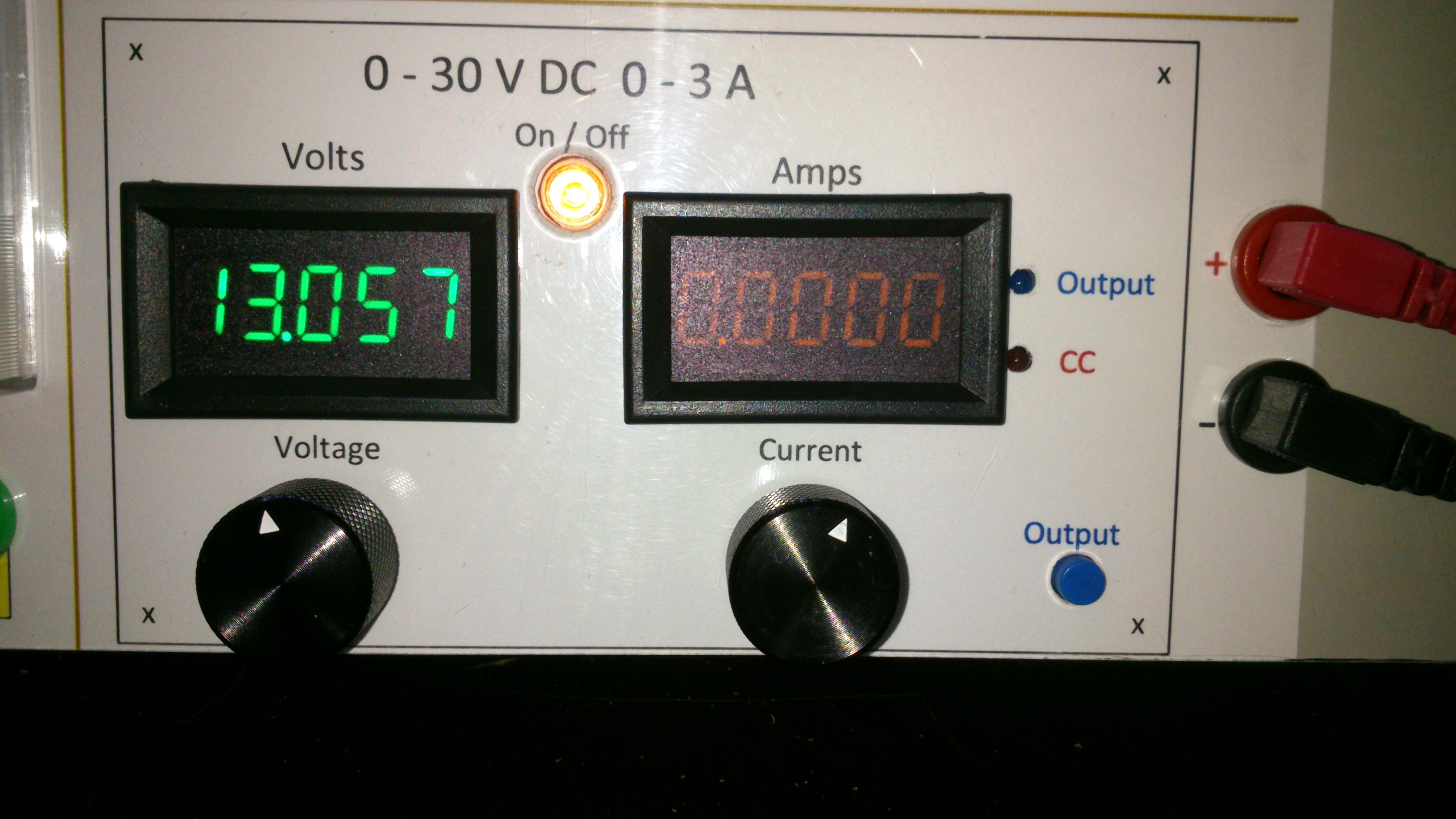
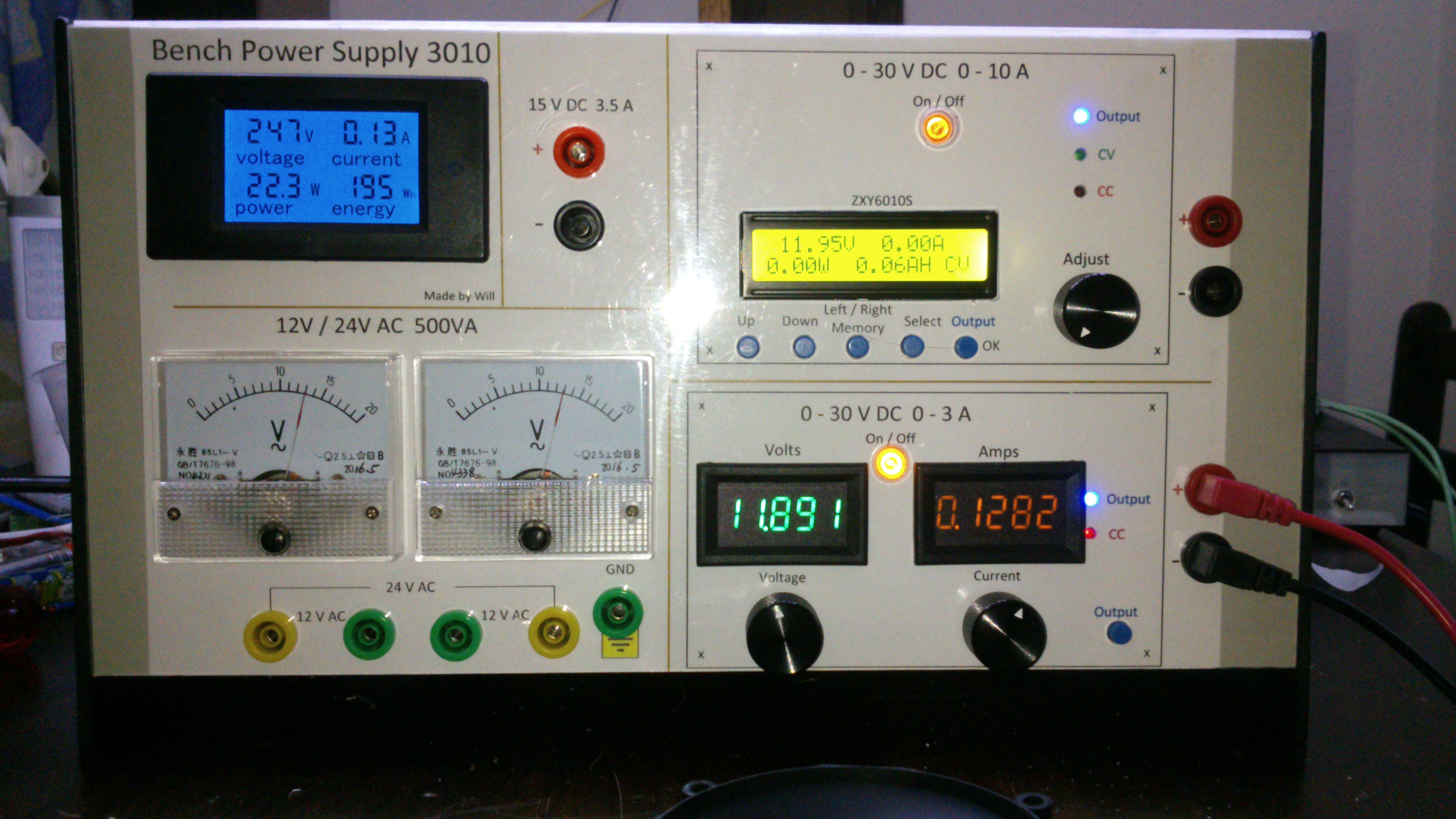
0-30V 0-3A Latest Data
AsSa and 3 others reacted to repairman2be for a topic
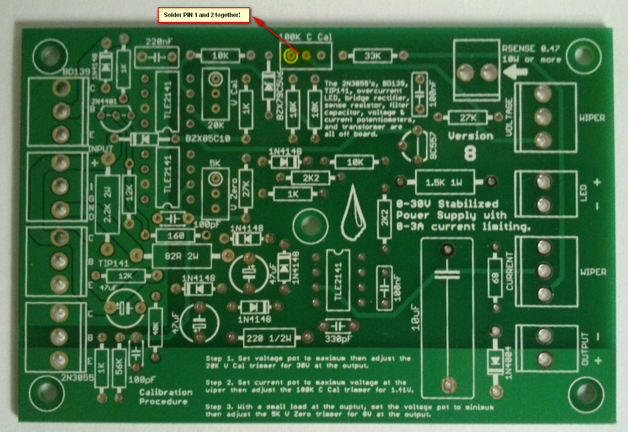
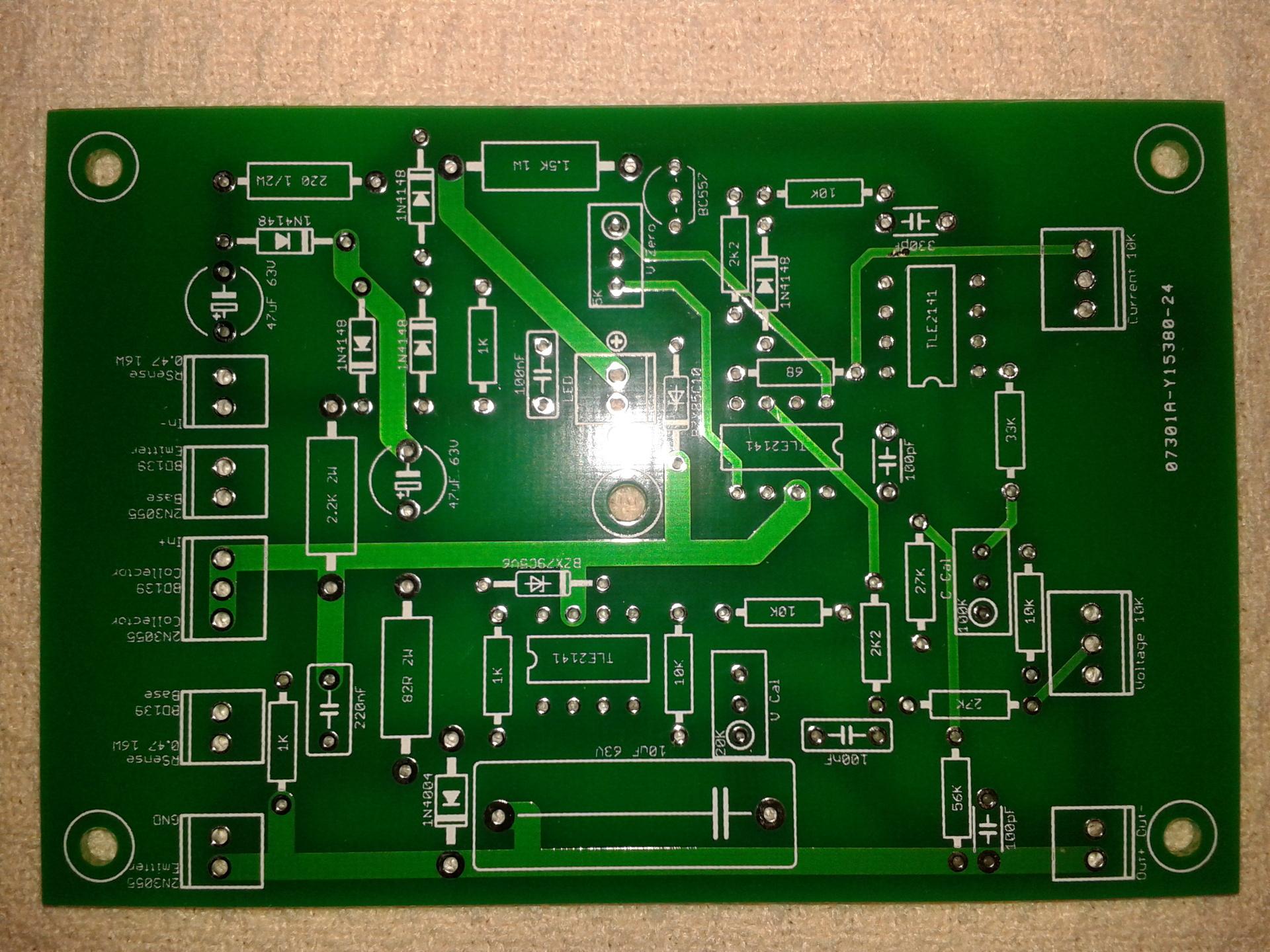
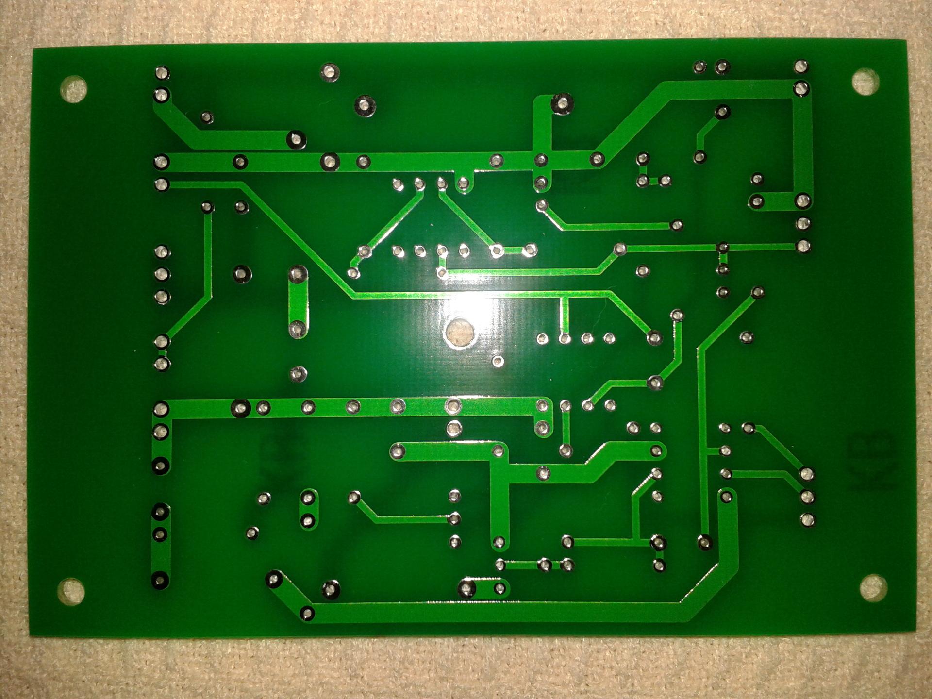
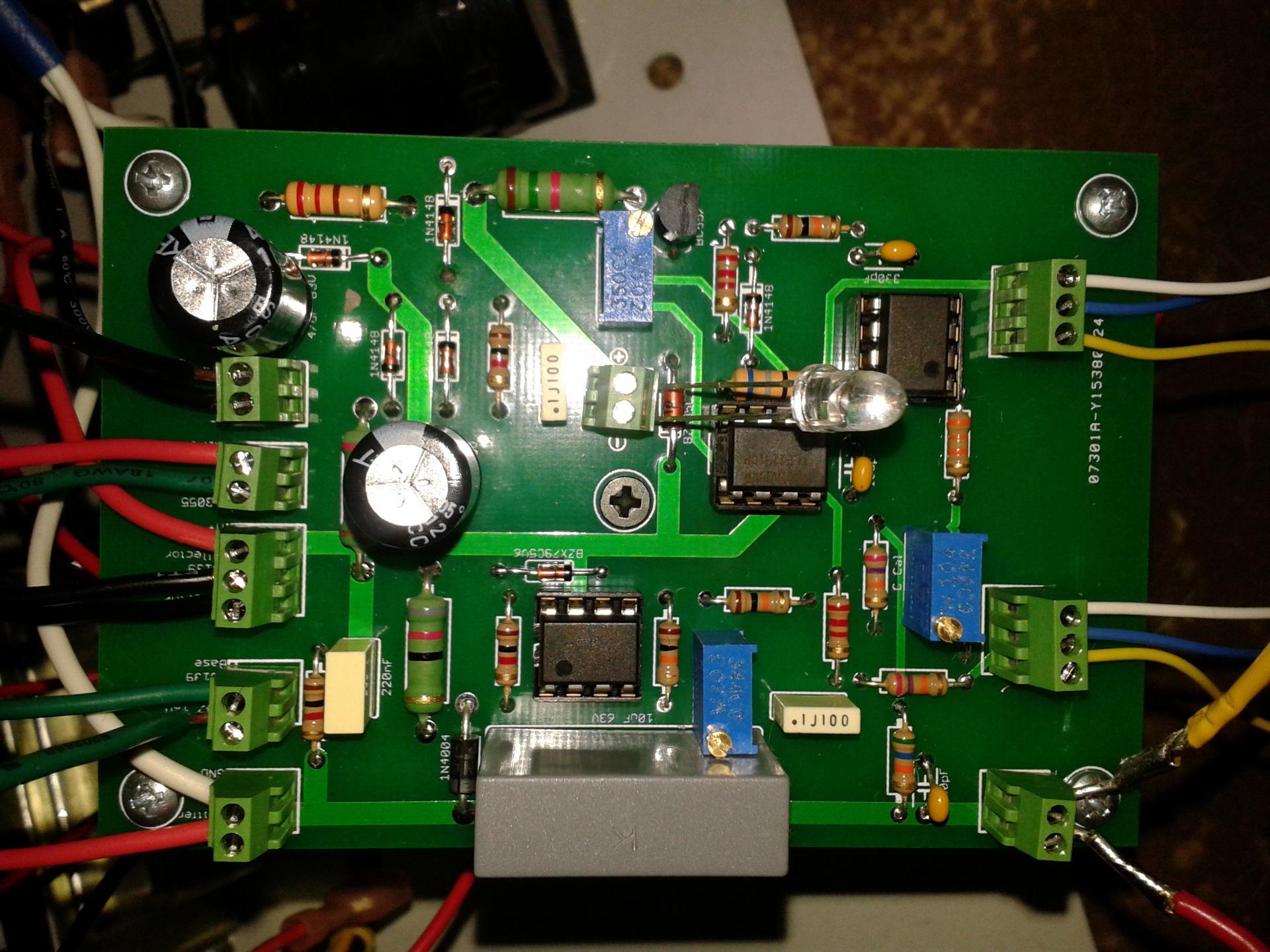
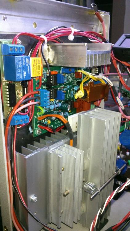
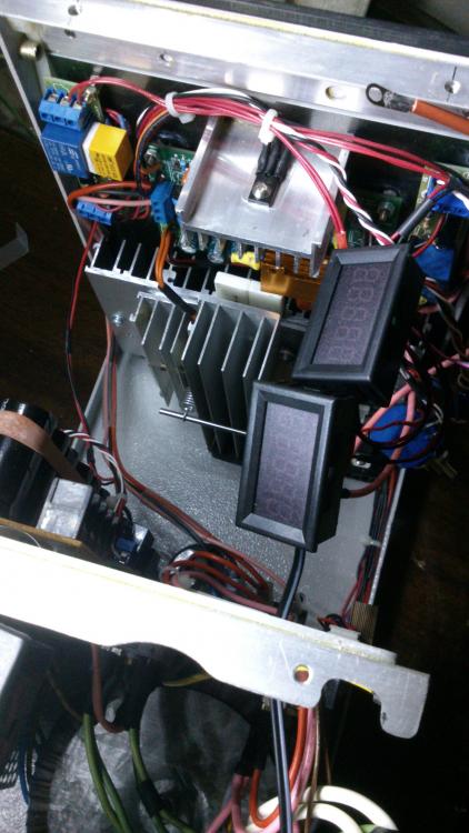
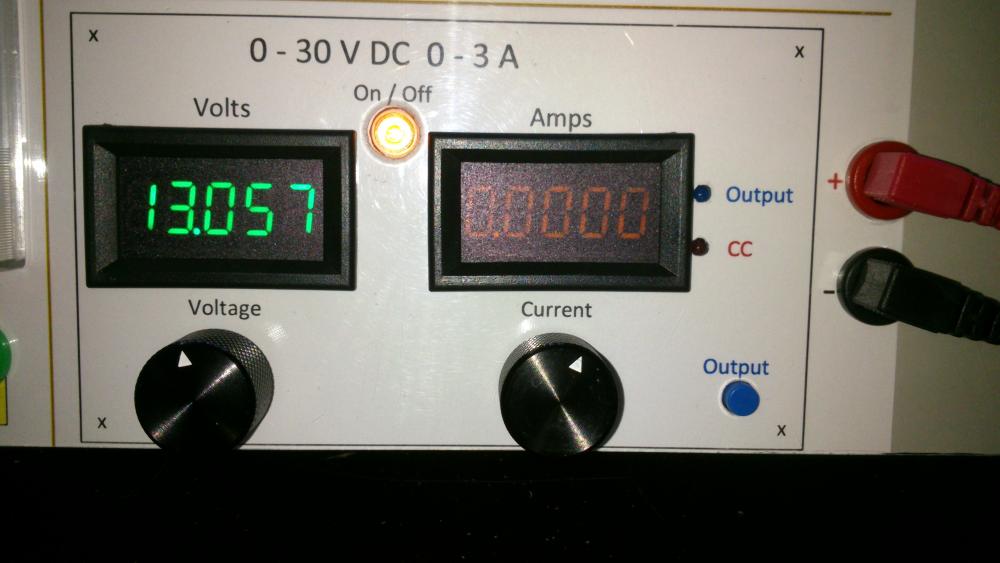
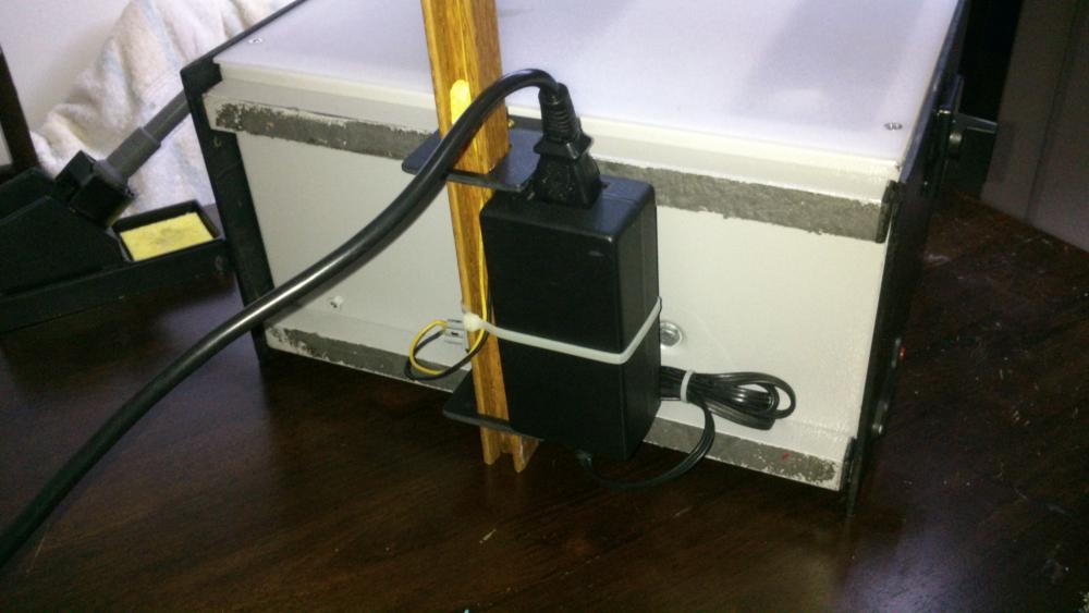
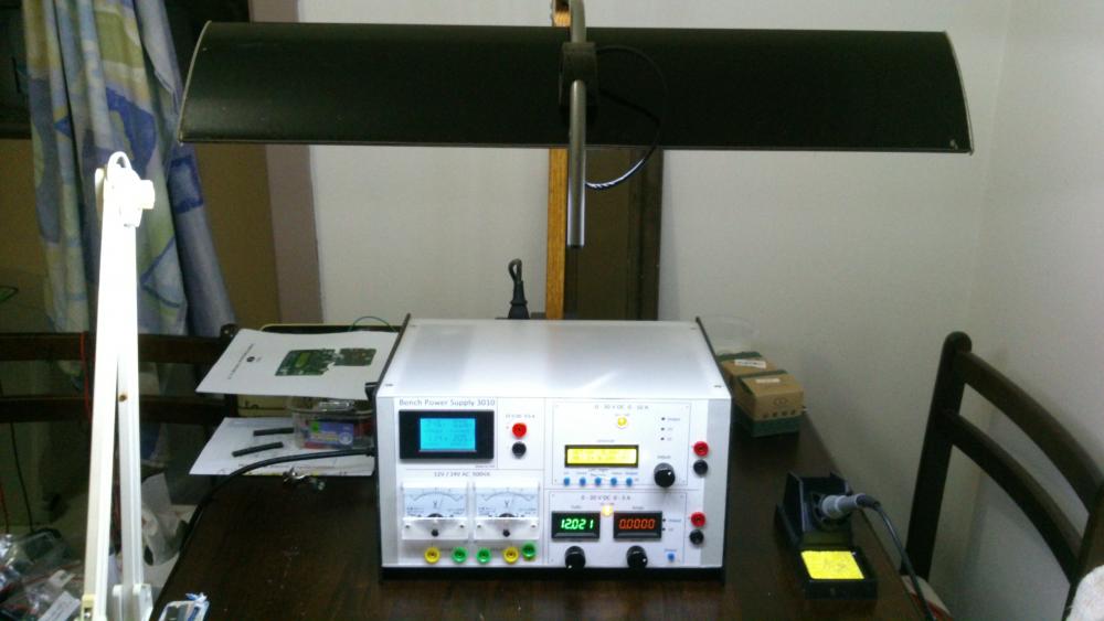
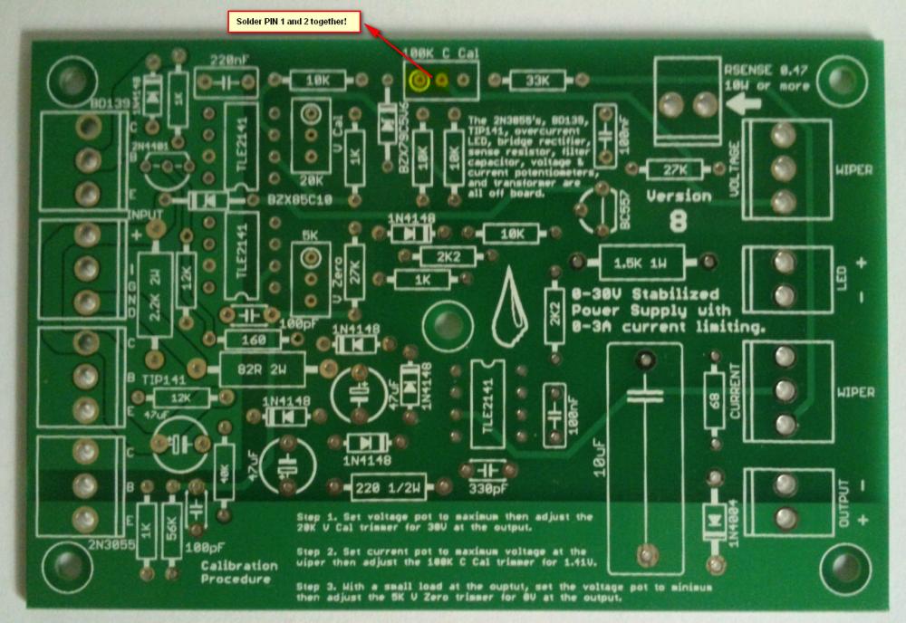
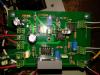
Hi all, Finally after some months have gone by, my build of the Power Supply is done. I have used liquibyte schematic Rev. 8 and had made the cirquit board according to the Gerber.zip file he posted here: 0-30V Stabilized Power Supply Page 88 posted October 6, 2014 "http://electronics-lab.com/community/index.php?/topic/29563-0-30v-stabilized-power-supply/&page=88" I left out D10 and R15 as per his description. I have plenty of boards leftover if someone has a need for it. There was only one mistake liquibyte made which have outlined in one of the pictures uploaded here. I was fortunate enough to get a big case with a Toroidal transformer from the scrapyard. Also many parts are recycled from various sources. Regards, William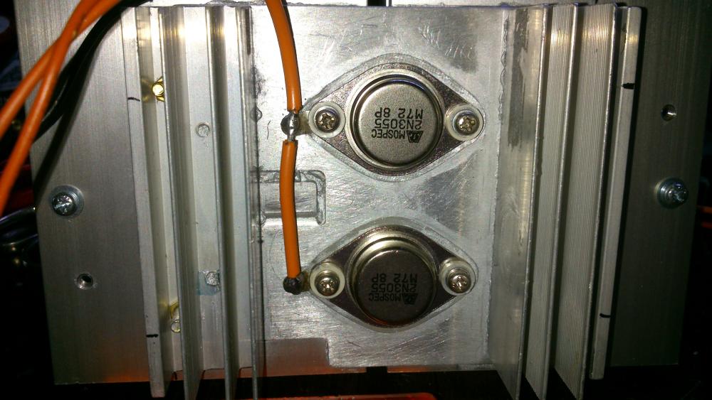

 4 points
 -
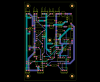
Finally, my post with the Eagle .sch and .brd, full gerbers, and parts list for Digikey in a zip file. I'm also including many of the pics I took as I was building that were posted both before and after this post. I'm still not completely done and may add more pics later. One thing I have changed is the third transformer for the auxiliary circuitry for the temperature sensor and fans and the displays (I wanted a better transformer than the Radio Shack special I had on hand). Archive attached. 30V.zip
 3 points
 -

Solar-powered Bee Hotel w/ Particle Argon (ongoing project)
Jolin He and one other reacted to JamesMVictoria for a topic
Nice one, I like it.2 points -

How to easily turn on/off all debug message on Arduino IDE
SharonWatkins and one other reacted to MrNams for a topic
But even if we disable debug, it will call print method and do not print anything. I mean we should make it something like #ifdef DEBUG Serial.print("\n debug controlled print"); #endif Here when we disable macro, its like code is not written for compiler, code will be removed in macro processing itself.2 points -

H Bridge PWM DC Motor Driver + PCB
senaka ranathunga and one other reacted to sam.moshiri for a topic
An H-Bridge (Full-Bridge) driver is quite popular in driving loads such as brushed DC motors and it is widely used in robotics and industry. The main advantages of using an H-Bridge driver are: high efficiency, rotation direction change, and braking the motor. In this article/video, I have introduced a complete H-Bridge DC motor driver using four IR3205 power MOSFETs and two IR2104 MOSFET drivers. Theoretically, the above-mentioned MOSFET can handle currents up to 80A, however, in practice we can expect to get currents up to 40A if the MOSFET temperature is kept as low as possible, using a big heatsink or even a fan. References Article: https://www.pcbway.com/blog/technology/Powerful_H_Bridge_DC_Motor_Driver.html [1]: IRF3205 Datasheet: http://www.irf.com/product-info/datasheets/data/irf3205.pdf [2]: IR2104 Datasheet: https://www.infineon.com/dgdl/Infineon-IR2104-DS-v01_00-EN.pdf?fileId=5546d462533600a4015355c7c1c31671 [3]: 1N5819 Datasheet: https://www.diodes.com/assets/Datasheets/ds23001.pdf [4]: IR2104 Schematic Symbol, PCB Footprint, 3D Model: https://componentsearchengine.com/part-view/IR2104PBF/Infineon [5]: IRF3205 Schematic Symbol, PCB Footprint, 3D Model: https://componentsearchengine.com/part-view/IRF3205ZPBF/Infineon [6]: CAD Plugins: https://www.samacsys.com/library-loader-help2 points -

Non Contact Hand Sanitizer Dispenser, Easy, Cheap, No Arduino!
sam.moshiri and one other reacted to admin for a topic
Thanks for sharing your project with us. Could you give more details on the control board?2 points -
The original circuit should work fine up to 15V at 1A if you replace the old opamps with the newer higher voltage ones. You probably should recalculate the resistors that set the maximum voltage and current outputs. If the Chinese kit uses the transistor that shorts the opamp output when the power is turned off then the resistors that feed the transistor need to be recalculated for the reduced voltage. I have used perforated stripboard for many projects including very complicated ones. The copper strips are cut to length with a drill-bit and become almost half the wiring of a pcb. The parts and a few short jumper wires become the remainder of the wiring. Only one wire is in each hole so changing a part is easy like on a pcb.2 points
-
Hi, as promised I made an English translation of my working. Maybe there is few mistakes and I am sorry for that ! Good reading. ExplicationEN.pdf2 points
-
I use copper wire, not rice wire. They put rice in everything they make, especially batteries.2 points
-

0-30 Vdc Stabilized Power Supply
electron234 and one other reacted to elctro123 for a topic
So Finally which version of schematic is correct / flawless to build the PSU ?2 points -
February 23 above on this page has the latest schematic of the revised 3A lab power supply.2 points
-
Does anyone has LM3914 pspice library? i desperately need it..pleeeeease!2 points
-

Low power solenoid?
AmelieScott and one other gave a reaction for a topic
I want to apply force for an extended amount of time (10 secs to a couple minutes) using a solenoid actuator. Unfortunately, it seems that solenoids use a lot of power when they are active. Is there a solenoid type that will only use power when switching between active and not active? There's probably a way I can do this with an external mechanism, but I was wondering if there may be commercial solenoids that have this built-in. Thanks, Jessica2 points -
Illegal content (ebook/magazines/software) will be deleted without any notice. Thanks2 points
-

Overload Protector A16 ???
joeydennis11 and one other reacted to tjolle62 for a topic
In a few circuit diagrams i have they refer to a what seems to me is a transistor with B C E as a overload protector and with number A16 and i have looked for a few hours on the net and i can't find anything on this little fellow, Anyone knows what I'm looking for and wanna share that info Please .... Come on !! 48 visits !! some one must know what it is !!! PNP is it also...........2 points -
Overload Protector A16 ???
joeydennis11 and one other reacted to tjolle62 for a topic
At last i got a theori from a totally different place and he wasn't shure either but he had a weak memory that it could be 1A16 and a PNP transistor but after several deep searches on the I-net it didn't make any kind of senses whatsoever ???2 points -

Car battery to parallel port
tracythomas50 and one other reacted to MP for a topic
When you use your resistive divider to drop the voltage down to 5 volts, you just need to select values of resistors to limit the current. This is basic ohm's law. V/R. Was this your question or did I misunderstand? I am not sure how you intend to monitor status by using one 5 volt pin. As an interface to the parallel port, you could use an LM3914. This would give you the resolution you need. There are also many other ways to proceed. You need to convert from analog to digital to read anything useful from the parallel port. MP2 points -

Car battery to parallel port
tracythomas50 and one other reacted to Omni for a topic
Hi TJBraza, http://www.analog.com/UploadedFiles/Data_Sheets/ADT7485A.pdf Although, it will probably require a small program written in C or Visual basic to convert the string MSB & LSB into a more easier read etc... Take a moment and review the data sheet, the IC has a lot of potential.2 points -

SL100 & SK100 transistor
AmelieScott and one other reacted to alanng96 for a topic
I can't find SL100 & SK100 transistor :'( Which transistors can replace these? Thank you for your help~ ;)2 points -
Calm down people. It is not Mixos's fault, if it is against the law he has to remove the content. This site is very good for asking electronic related questions, I have yet to find a better one.2 points
-

W25Q32JV FUNCTIONAL DESCRIPTIONS
Veswin reacted to Blunt Viscardi for a topic
W25Q32 refers to a specific model of serial flash memory produced by Winbond Electronics Corporation. In particular, the "W25Q32" is part of the W25Q series, which consists of a range of flash memory chips differing in capacity and features. Standard SPI Instructions: The W25Q32JV is accessed through an SPI-compatible bus consisting of four signals: Serial Clock (CLK), Chip Select (/CS), Serial Data Input (DI), and Serial Data Output (DO). Standard SPI instructions use the DI input pin to serially write instructions, addresses, or data to the device on the rising edge of CLK. The DO output pin reads data or status from the device on the falling edge of CLK. SPI bus operation Mode 0 (0,0) and 3 (1,1) are supported. The primary difference between Mode 0 and Mode 3 concerns the normal state of the CLK signal when the SPI bus master is on standby and data is not being transferred to the Serial Flash. For Mode 0, the CLK signal is typically low on the falling and rising edges of /CS. For Mode 3, the CLK signal is usually high on the falling and rising edges of /CS. Dual SPI Instructions: The W25Q32JV supports Dual SPI operation when using instructions such as "Fast Read Dual Output (3Bh)" and "Fast Read Dual I/O (BBh)". These instructions allow data to be transferred to or from the device at two to three times the rate of ordinary Serial Flash devices. The Dual SPI Read instructions are ideal for quickly downloading code to RAM upon power-up (code-shadowing) or for executing non-speed-critical code directly from the SPI bus (XIP). When using Dual SPI instructions, the DI and DO pins become bidirectional I/O pins: IO0 and IO1.1 point -

Electronic flourescent tube starter
Soren Thompson reacted to HarryA for a topic
I am confused with the two SIDACs (Silicon Diode for Alternating Current) in series. They are rated 220-250 volts switching each. 240 mains voltages would be in the order of 340*1,4 or 480 volts peak. About the same as the two SIDACs; not much to switch with? "These tasks of the starter are taken over by two 135 V sidac (or a single 270 V one). The starting voltage is thus 270 V, Which is below the peak value of the mains (about 340 V), but higher than the working voltage of a 20-40 W neon tube." see: https://circuit-diagramz.com/sidac-neon-tube-starter/ I will look at the circuit some more.1 point -

555 timer
JaneCai reacted to Holy Hathaway for a topic
The 555 timer is a medium-sized integrated circuit developed by Signetics in 1972 to replace mechanical timers. It is named after the input is designed with three 5kΩ resistors. This circuit later became popular in the world. At present, there are four popular products: two BJTs: 555, 556 (with two 555); two CMOS: 7555, 7556 (containing two 7555). The 555 Timer is a mid-scale integrated device that combines analog and digital functions. It is called 555, which is usually fabricated by bipolar (TTL) process. It is called 7555 by complementary metal oxide (CMOS) process. In addition to single timer, there is corresponding double timer 556/7556. Its power supply voltage range is wide and can operate from 4.5V to 16V, the 7555 can operate from 3 to 18V, and the output drive current is approximately 200mA, so its output is compatible with TTL, CMOS or analog circuit levels. The 555 chip is an extremely versatile chip with up to hundreds of different applications including time-base timing or switching and voltage controlled oscillators and regulators. For those who have been exposed to digital or analog circuits, the 555 chip is definitely a classic. With its low cost and reliable performance, it is widely used in various electrical appliances, including instrumentation, household appliances, electric toys, and automatic control. Its various pin functions are as follows: Pin 1: external power supply negative terminal VSS or ground, under normal grounding. Pin 2: Low trigger terminal TL, this pin voltage is valid when it is less than 1/3 VCC. Pin 3: output OUT. Pin 4: directly clear the terminal RST. When this terminal is connected to a low level, the time base circuit does not work. At this time, regardless of the level of TL and TH, the time base circuit output is “0”, and the terminal should be connected to a high level during normal operation. Pin 5: CO is the control voltage terminal. If the pin is externally connected, the reference voltage of the two internal comparators can be changed. When the pin is not used, the pin should be grounded into a 0.01μF (103) ceramic capacitor to prevent high frequency interference. Pin 6: High trigger terminal TH, this pin is valid when the voltage is greater than 2/3 VCC. Pin 7: discharge end. This terminal is connected to the collector of the discharge tube T and serves as a discharge pin for the capacitor at the time of the timer. Pin 8: external power supply VCC, bipolar time base circuit VCC range is 4.5 -16V, CMOS type time base circuit VCC range is 3-18V, generally 5V. 1 point
 -
Can I replace MPXV7002DP transducer by MPXV7002DPT1?
Holy Hathaway reacted to HarryA for a topic
This site gives the MPXV7002DPT1 as an alternative to the MPXV7002DP see: https://www.apogeeweb.net/circuitry/mpxv7002dp-transducer-datasheet-features-pinout.html#product-overview This one has a list of exact alternatives also: https://www.newark.com/nxp/mpxv7002dpt1/pressure-sensor-2-to-2kpa-sop/dp/28X37171 point -
If it is a 120 volt Cuisinart blender then you can get one here: They ship world wide. Else search for "1 uf 250vac capacitor" https://www.ebay.com/itm/281873849657 That is a horrible url !1 point
-
That looks correct. Good job with the simulator.1 point
-

BMS Charger for 18650
gztoppower reacted to arielrizuly for a topic
Need info for scheme bms 12v I -[===]+ -[===]+ -[===]+ l I -[===]+ -[===]+ -[===]+ l I -[===]+ -[===]+ -[===]+ l I. I I. I I. I 12v - 12v +1 point -
The LM3914 in a DIP case is not made anymore. Buy them before they are all gone.1 point
-
I enlarged the image off the Amazon.com but could not read it https://www.amazon.com/Black-Decker-LCS1620-Lithium-battery/dp/B01M6TQPY2/ref=sr_1_3/141-0275392-4037060?ie=UTF8&qid=1499813460&sr=8-3&keywords=Black+%26+Decker+LCS1620 ...but ebay.com has a readable image http://www.ebay.com/itm/Black-Decker-LCS1620-20v-20-Volt-Lithum-Ion-Battery-Charger-NEW-/272090041874?epid=1640405275&hash=item3f59d48e12:g:mf8AAOSwawpXr3eh 120v @60hz 300ma1 point
-
hi any updates to this project1 point
-

PCB manufactureres
rrp0727 reacted to Soldertraining for a topic
PCB Manufacturer uses: Front-end tool data preparation, Preparing the photo tools, Print inner layers, Etch inner layers, Register punch and Automatic Optical Inspection (AOI), Lay-up and bond, Drilling the PCB, Electroless copper deposition, Image the outer layers, Plating, Apply solder mask, Silk-screen and cure.1 point -

Power supply
soldertools1 reacted to audioguru for a topic
You forgot to say if the 10V output from your power supply must be AC or DC. You also forgot to say if the input is AC or DC and its voltage and frequency. Did you know that the output power from your power supply will be 10V x 1000A= 10000 Watts? Where will it come from? What will it be used for?1 point -

12v lamp Dimmer lamp ideas?
Jordan&tiffany reacted to stuee for a topic
I have a 12v transformer for interior lights and a few lights for it, but want to make it a dimmer light. the working amps are 250mA. I would like to know how to wire up these three ways, so i can try each one and see if its any good and use the best.... Touch lamp. touch the metal to turn on dimmest. press again for brighter and again for brighter and again for off. Manual pot adjuster. and digital potentimeter. press up to turn up and make brighter and down for darker / off, and a reset button to turn instant off. Any help and sche... will be helpfull. Thanks in advance1 point -

Need help with a project
sam g fire reacted to jknightandkarr for a topic
I am trying to make this KITT's dash compass andi have the leds and using a microcontroller to power them but need help on how to wire them so i use the least amount of conponents possable. I thought of darlington transistor ic's but on the 4 10 led bargraph onesi think both anode n cathode will need darlington transistors. 4 1 for either common cathode or anode and 10 more for the other lead for make the patterns. I might be able to use 1 darlington transistor ic to make the yellow triangle leds work using just 4 i/o pins, but i think i need 14 for the red bargraps whats the best way to wire the bargraph leds up? Thanks. Joe1 point -

An Ultrasonic Cleaner--Schematic
FranceRouze reacted to GOKAR for a topic
Looking for an Ultrasonic Cleaner schematic. Gokar1 point -
About 53 years ago the CD4046A was introduced but it had many problems. It was replaced a few years later by the improved CD4046B and MC4046B and HEF4046B. Your CD4046A must be one of the very old ones with problems. Look on the datasheets of an A and of a B to see the differences.1 point
-
LM3914 pspice library
joeydennis11 reacted to admin for a topic
Here are two SPICE models found online that will simulate the main IC functions including:- a) bar/dot mode selection, dot mode carry for cascaded ICs, c) resistor-programmed hi/lo reference voltages, d) output current selection, e) non-grounded V- and divider ladder, f) independent V+ and Vled, g) leakage current of outputs, h) segment overlap and i) supply current variation with V+ and Vref output load. This model is build by user "alec_t" at electro-tech-online.com forum. LM3914.zip LM3914asc.zip1 point -
i am designing radio transmitter and reciever
ravikumarmangalampalli gave a reaction for a topic
parts i have : antenna wire,magnetic wire,toroid core, 23 mhz crysrtal oscillator,some transistors ,resistors,capacitors.... i want to design circuit to simply on and off the led by radio waves. could u sugest me simple circuit with to do this.. plzz.thank you in adavance1 point -
0-30V 0-3A Latest Data
navidmomeni gave a reaction for a topic
Continued
 1 point
 -
0-30V 0-3A Latest Data
navidmomeni gave a reaction for a topic
Continued
 1 point
 -

PWM using 555 timer
FranceRouze reacted to darrins for a topic
I read several datasheets and application notes on 555 timers, but I can't seem to find the information I'm looking for. Specifically, I'd like to use the 555 as a pulse width modulator by using the control voltage (pin 5). The datasheets indicate that in monostable mode, the output pulse width can be varied by modulating the voltage at pin 5 (V5). They also indicate that in astable mode, modulating V5 will modulate pulse position. What I'm wondering is this: What is the relationship between the control voltage, V5, and the values of the timing resistors and caps? There are standard formulas for timing based on these resistors and caps. How are those formulas affected by the introduction of V5? Thanks. Darrin1 point -

2n2222 resistor value
Sidney Bell reacted to eplanet for a topic
thanks hero999 is there any formula for this issue? my coil is 57ohm1 point -

High Voltage low amperage
HaddyS reacted to Silent Jack for a topic
No, lead acid batteries are far too heavy. I was looking at maybe NiMH or more likely some LiPo batteries commonly used on RC cars and the like. Looking at 3-6AmpH class batteries. Might lean towards 12V, since there is so much standard stuff for that as far as wiring and other components. Safety is of course important and any good suggestions on grounding/shielding are welcome and appreciated.1 point -

High Voltage low amperage
HaddyS reacted to Kevin Weddle for a topic
A transformer will deliver a high enough voltage that you want. High voltage transformers are expensive, but can usually be found in electronics products no longer used, and be cascaded for high voltgage. Be aware that high voltage burns and shock can occur, and a high enough voltage can lay you in the hospital.1 point -
Possibly a flyback converter? They can usually be output current limited by limiting the current availiable to the transformer. Do you need it to be highly efficient or are you not too fussed?1 point
-
Electronic suplus stores
Jordan&tiffany reacted to gogo2520 for a topic
Hello RFamateur and welcome to the form. Here are a few. These have stuff some good lot outdated. http://www.goldmine-elec.com/default.htm http://unicornelectronics.com/prod.htm http://www.mpja.com/category/LEDs/LEDs.asp http://www.futurlec.com/index.shtml http://www.allelectronics.com/ http://www.danssmallpartsandkits.net/ http://www.alltronics.com/assortments.htm These are good suppliers http://www.mouser.com/index.cfm?handler=home http://www.futureelectronics.com/en/Pages/index.aspx http://www.web-tronics.com/ http://www.jameco.com/webapp/wcs/stores/servlet/StoreCatalogDisplay?storeId=10001&catalogId=10001&langId=-1 That should get you going. gogo1 point -

An excellent electronics manual
Jordan&tiffany reacted to CornToeNo for a topic
Here is the book in pdf for you all. You can press the free button and you have to wait about a minute then it gives you the links. Just pick one. http://rapidshare.com/files/3372603/Practical_Electronics_for_Inventors.pdf1 point -
Pin 8 of the IC should be 5.0V which is the output of the 78L05 voltage regulator or the 6V battery voltage. If you use the voltage regulator and D1 in series with it, then the minimum input voltage is 8.2V. Don't use a 9V battery because its voltage quickly falls lower. The micromitter has an attenuator of 3 resistors at its output to reduce its range. Remove the attenuator for much greater range.1 point
-
Think of the commas as periods or the periods as commas. These are used differently in different continents. It means the same. MP1 point
-
I attach it here also for fast view...1 point