admin
-
Posts
180 -
Joined
-
Last visited
-
Days Won
5
Content Type
Profiles
Forums
Events
Everything posted by admin
-
Hi Peter and welcome to the community. Could you share your thoughts building this LC meter and if everything worked right from the beginning.
-
Hi and welcome to elab community Could you post a photo or diagram of what you are trying to do?
-
I came across 2 builds of this power supply with lot's of info on the process and tuning of it. http://diyfan.blogspot.com/2012/02/adjustable-lab-power-supply.html http://www.paulvdiyblogs.net/2015/05/tuning-030v-dc-with-03a-psu-diy-kit.html Worth checking these websites.
-
Welcome back ELECTROMAGIX, much has changed since your post above. Feel free to share any details about this interesting charger.
-
You have to give us more information so we will be able to help.
-
Hi Shuhrat, We are an English speaking community here. Please post in English so anyone can understand.
-
Excellent measurements! Thanks for sharing.
-
Hi Tintin, You have done excellent work building this power supply and your experience is valuable for all other members. I encourage you to translate the PDF in English so anyone can benefit from it. Looking forward seeing your measurements and thoughts building this PSU.
-
Hi and welcome to our community, To help you out we will need more information about your connections and software used. A clear schematic will help us locate any issue and your code will provide additional insight.
-
Hi, To achieve what you would like you need a programmable timer to be able to set the ON-OFF time at high precision. I don't know if you can find such timer in the market, as most timers are rated about 16A and are weekly programmable. What possibly you could do is to use a timer to set the ON time and keep the OFF time manually. In this case a timer like: http://www.electronics-lab.com/project/2-digit-99-seconds-timer/ http://www.electronics-lab.com/project/1-to-100-seconds-timer/ may help.
-
I would be perfect if you share your review building this PSU with other members on the community.
-

DIY - ARDUINO BASED CAR PARKING ASSISTANT
admin replied to Ashish Adhikari's topic in Electronic Projects Design/Ideas
Thanks for sharing this project. I just edited it a bit, so code would look better.- 7 replies
-
- 1
-

-
- arduino
- ultrasonic sensor
- (and 1 more)
-
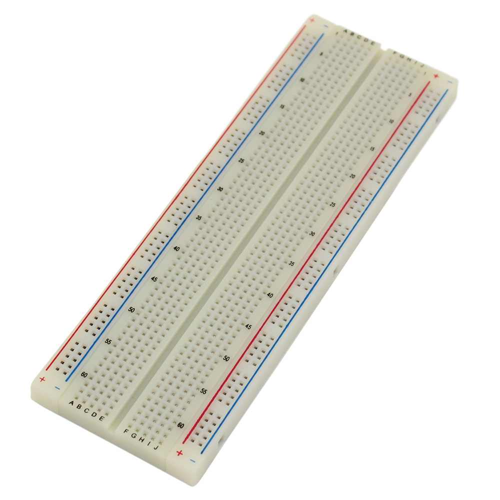
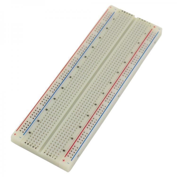
Is this something like the photo below? These are called "breadboards" and comes in different sizes. They have the pins in a row connected together so they are used to create various circuits by plugging the components.
-
He will need something more powerful at least for the 16Vdc rail. Something like the LT3845A, which has 60V input voltage and 15A output current may work for this application. Datasheet: https://www.mouser.com/ds/2/609/3845afa-1270855.pdf
-
how to design a battery jack for unknow phones
admin replied to mohamad7419's topic in Power Electronics
We will need more info, so we are able to help. -
Hi and welcome to our forum, I would like to let you know that we have featured your campaign to our blog: http://www.electronics-lab.com/isolated-usb-uart-converter-arduino-pro-mini/ Hope you like it. Best Regards
-
Can you be more specific on what you would like to achieve?
-
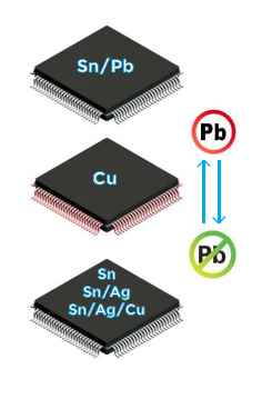
OEMsecrets Partners with Retronix to enable IC Testing services. Retronix are considered to be one of the industry leaders in IC testing services. They offer a unique set of technology solutions and can test any components you purchase whilst also offering alloy conversion if you cannot find your part in the specified alloy. To support obsolete components listed by verified non-authorised distributors on OEMsecrets, users can now request testing services by clicking the "IC Test" icon, located in the specs column of the search results on OEMsecrets.com. OEMsecrets is a free to use price comparison search engine for electronic parts and components, listing inventory and pricing information from suppliers such as Avnet, Arrow, Digikey, TTI, Farnell and many more. Learn more: https://www.oemsecrets.com & http://www.retronix.com/oem-secrets-retronix/


-
Can you please check now and report back? We have done some updates on the community software.
-
Thanks for reporting this issue. I will check and get back to you.
-
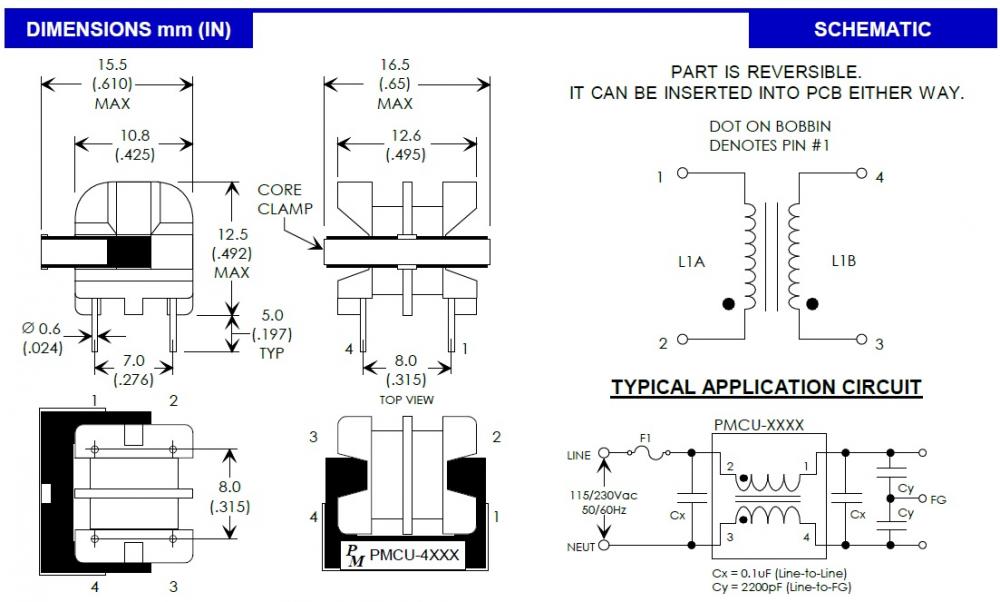
This topic is to clarify the specs of T1 transformer used in http://www.electronics-lab.com/project/power-supply-brushless-motor-drivers/ T1 is a Standard EMI/RFI Transformer for electromagnetic noise, any 15/16mm transformer with 1mH inductance will work. This transformer is used to reduce EMI/RFI noise and doesn't provide isolation from mains voltage. I am attaching here the datasheet of the transformer. pmcu.pdf
-
Hi and welcome to our community! Feel free to start a new topic about your project/question etc
-
A modern day 0 - 30V, 0 - 3A Linear Power Supply?
admin replied to repairman2be's topic in Projects Q/A
You may check this blog for a revised version of the popular 0-30V PSU: http://www.paulvdiyblogs.net/2015/05/tuning-030v-dc-with-03a-psu-diy-kit.html -
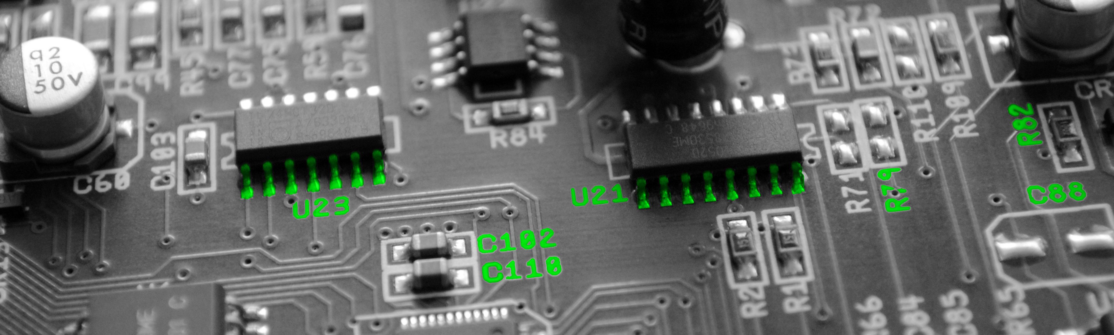
These also seems like capacitors to me. I also found a chart that looks pretty close to their marking.
-
The diode is needed for the circuit to work, otherwise you may damage the IC or your load. Without this diode the switching of LM2596 can't occur. You may use IN5822 schottky diode or another 3A schottky diode.