

narog
-
Posts
2 -
Joined
-
Last visited
Never
Content Type
Profiles
Forums
Events
Posts posted by narog
-
-
Hello.
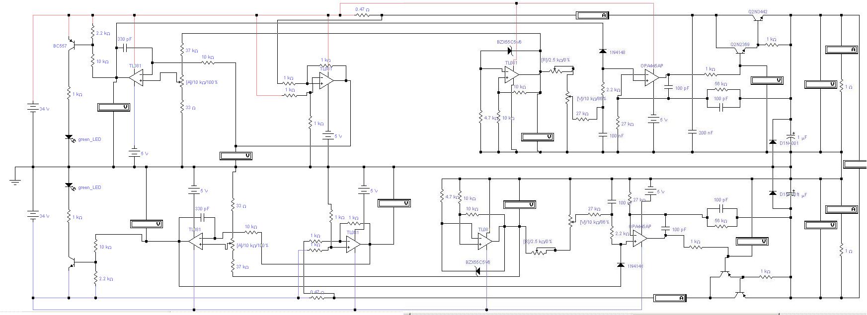
I am electronic engineering student and for 3 weeks I have been studding this power supply. Now I understand 98% of the PSU, and I decided to design a symmetric PSU. Here is my schematic. This is not a finished job, but maybe can help you. If you have Electronics Workbench you can simulated and maybe understand how it works.
Right now this schematic has a big problem in the current limiter. The problem is very simple the current limiter only works if the load is connected to ground. If you have a load connected to +32 -32 V the PSU don’t work very well. Maybe some one can help and figure the solution out.
Sorry I am Portuguese and my English is not the best.
Convert 0-30V 3A PSU to 5A or more
in Electronic Projects Design/Ideas
Posted
Hi, the transistor/Ampops in the schematic are not the final ones. These components are there only for simulation.
The Electronics Workbench has a big library but is a little old.
The power transistor has to be symmetric so I have been search the web and I found:
NPN 2n5631 PNP 2n6031 16A 140V 200W
NPN 2n3772 PNP 2n6609 16A 140 V 150W
NPN 2n3055 PNP MJ2955 15A 90V 114W
For current sense and voltage reference generator ampops you can use tl081 if you build a regulated power supply of 15V 0V -15V, “LM7815 LM7915” this is because the opa445AP cost 8.40euros “Portugal Price”.
For the 2n2369 sorry, my mistake…..
The positive current sense is well connected, but in the schematic you cant see that. The wires are very close, sorry. For the negative one I need a negative output. If you invert the inputs the ampop will not give you – X.XX V because -31.74V – (-34V) = 2.26V and not -2.26V.
Thanks audioguru.