

Shahriar
-
Posts
451 -
Joined
-
Last visited
Content Type
Profiles
Forums
Events
Everything posted by Shahriar
-
 Hi Does anybody know what kind of sensor (photo diode) manufacturer uses in Red light photo electric sensor? Specially receiver? I have found BPW34, but think manufacturers uses something else. Look at this through beam from Optex https://www.optex-ramco.com/index.php?route=product/product&product_id=2066&search=Ctd-2500&description=true Thanks Shahriar
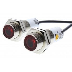
-
Dear Hero Yeahhhh, Thats right ;D it has a Power factor corection module that boost the voltage to 424V for the main PSU. It is made by MC33262P Controller. I Had never seen such PFC circuitry before. That was nice experience! This is the Topology I thought: and this is what it really was: and this is the PFC schematic: The Vizz sound is coming out from PFC Transformer. and it is still out there! I have replace the 1uF Cap (C5), but no difference :-\ Do u have any Idea? Shahriar
-
Hi I am somehow familiar with SMPS troubleshooting; But today I have encountered a strange problem It is 48v, 150W SMPS with UC2844 Controller. The first problem was the output was low (around 42V) I Replaced the 47uF on Vcc pin of the UC2844 and everything got OK But still a small Vizz Sound can be heard from the SMPS The Most strange thing I see is the voltage on the Bulk Capacitor after diode bridge (220uF, 450V) I expect a voltage around 320V on this Cap, but the voltage I read is 424V. I have tested the RCD Snubber circuit but didn't see any failure. And I think the Vizz problem is somehow related to this extra high voltage. Have u ever seen such thing? ThanX In advance Shahriar
-
Hi Today I saw these Swimming competition touchpads Manual (Attached file) and I am wondering how these touchpads work! it the Manual it has written :"The touchpads use a proven design incorporating three conductive plates made of non-corrosive stainless steel to provide years of reliable service. The stainless steel front and intermediate plates fex easily when touched by the swimmer. Resilient strips of insulating acrylic foam tape separate each plate. while the touchpads are highly sensitive across the the top and front, they are tough enough to keep wave action from activating the plate" the Size of panel is 90cm x 240 I have attached the Manual too; ThanX in advance Shahriar SL10421.pdf
-
Hi I have attached a valuable SMPS Design with TEA1507 Controller; Can anybody tell what do those C5=2.2nF, R4,R5=4M7 do there? (Page 26, In the Main Circuit diagram) ThanX in advance Shahiar 66B6002Cd01.pdf
-
Balance Microphone amplifier
Shahriar replied to Shahriar's topic in Electronic Projects Design/Ideas
So what is the solution? It is impossible to mount the mic somewhere else; we can change the mic, we can change the circuits but we can NOT attach a mic to the doctor! What would you do if want to design such circuit? thanX shahriar -
Balance Microphone amplifier
Shahriar replied to Shahriar's topic in Electronic Projects Design/Ideas
Yeah Now that you are saying, the problem is the mic is too far away from the voices so that the sound is mostly echoes; just those part of sound which is louder can be heard; the distance between the electret mic and doctor is about 2-3m Should we add an AGC circuit? ThanX Shahriar -
Hi I am working in an hospital. there we have a room where doctors are isolated from nurses because of the X-ray. But sometimes doctors should talk to nurses. this is done by a small condenser Microphone mounted on the ceiling (On Top of the doctor head) and a pair of PC speakers in the nurses room. the distance between the Mic and Speaker is around 12 meters and I think this is why nurses can not hear what the doctor say clearly; I think If I use an amplifier completely close to the Mic and convert its output to a balance output, then send the balance output to a differential amplifier in the nurses room, then we can have a more clean sound! What do U think? Can anybody tell me how can I convert the condenser Mic output to a balance output? Here's a pic of what I plan to do. ThanX Shahriar
-
Are these two circuits equal?
Shahriar replied to Shahriar's topic in Electronic Projects Design/Ideas
Hi I didn't know there are such regulators on the market! ::) I will definitely use them in future thanX Shahriar -
Are these two circuits equal?
Shahriar replied to Shahriar's topic in Electronic Projects Design/Ideas
Dear audioguru when you are to power an MCU based or a sensitive device from an iginition power supply, i.e. when connecting your circuit to a Car, because of high transient voltage (upto 60v) you can not just use 7805 and some capacitors; if you search between the car CD players you can always see an inductor around 800uH before the regulator and some caps around it; without this inductor, you will have crash! now if you are conviced, can you tell me Do those two circuits (I attached) differs? thanX Shahriar -
Are these two circuits equal?
Shahriar replied to Shahriar's topic in Electronic Projects Design/Ideas
Dear audioguru Ok, put two caps around the regulator; Not important for this question! ;) I just mean what would happen for the output if we change the Inductors position? ThanX shahriar -
Hi Are the outputs of these two circuits different or they are the same if Vin is 12VDC with some noises (i.e. from an Ignition Motor) L1 and L2 are completely seperate and wounded on different cores! ThanX Shahriar
-
Redesign Elektor gigant2000 Amplifier
Shahriar replied to Shahriar's topic in Electronic Projects Design/Ideas
Can You give few examples of resistors you believe to be calculated again except those I Said. ThanX Shahriar -
Redesign Elektor gigant2000 Amplifier
Shahriar replied to Shahriar's topic in Electronic Projects Design/Ideas
ThanK you for your reply and your calculation. I Think It is because of our different explanations of Class A. Can You help me to Lower the output of this Power amplifier. Tell me If I am right: I want to decrease The 78V regulated supply to 30V and 70V Unregulated to 25V. (I have a 3-way cross over circuit and want to use this Amp for it) 1- I will reduce R22, R23 (3K3) to 680ohm. 2- I will reduce R19, R21 (10K) to 2K2 But I have No Idea about Which Transistor to remove among T15-T26 and T29-T34 If I use Just Two Output transistor (i.e T35 & T39) ThanX in advance Shahriar:rolleyes: -
Redesign Elektor gigant2000 Amplifier
Shahriar replied to Shahriar's topic in Electronic Projects Design/Ideas
90mA quiescent current for each Transistor is not Low. It is said that when your Amplifier is playing, Try to Increase Bias current to convert it from Class AB to Class A, Then You will Understand the difference in Details! I have just heard it, Not tested. But I think It is really depending on Your Speakers. Without good Speaker, It is just wast of time. Shahriar -
Redesign Elektor gigant2000 Amplifier
Shahriar replied to Shahriar's topic in Electronic Projects Design/Ideas
But All of the famouse Brands are biased in Class A with Big Heat Sink to avoid Distortion (Denon, Accuphase and ...) . Class AB is used in Usual Systems like JVC, SONY, LG and ... Dear Audioguru Can You Help me with this design? :D Shahriar -
Redesign Elektor gigant2000 Amplifier
Shahriar replied to Shahriar's topic in Electronic Projects Design/Ideas
I Don't think those Ics have such Specifications. after all, I think Most of them are in Class AB. I Just want to reduce the Output power to reduce extra heat and Price. ThanX in advance Shahriar\ -
Redesign Elektor gigant2000 Amplifier
Shahriar replied to Shahriar's topic in Electronic Projects Design/Ideas
sorry ??? Here the link: http://www.corradodriver.de/HTML/Elektronik/Gigant2000/Gigant1.htm (click The pictures) Shahriar -
Hi I Love Accuphase Amplifier topology very much and it is long time I am trying to find a good schematic. I found Elektor gigant2000 design very similar to Accuphase. But I Need a Lower power Design. Can Anybody tell me how is possible to redesign it for 50 to 60Watt. I Know some what to do, But I affraid to Miss something and can't get the result. Here a link to German site which contains the schematic http://www.corradodriver.de/HTML/El...000/Gigant1.htm ThanX Shahriar
-
Replacing IGBTs with BJTs in Elektor IGBT design!
Shahriar replied to Shahriar's topic in Electronic Projects Design/Ideas
The original design is from Elektor Magazine, may 1997issue fortunately I have another schematic which a nice guy has redraw it. http://www.4shared.com/file/10940178/f870121/giesigbt.html This designer have many designs that the output is connected to Power transitors Collector instead of Emitter via resistors. This is why there is no resistor. ThanX Shahriar -
Hi I read Reviews about IGBTs, MosFETs and BJTs uses in Audio Power amplifiers. I want to build the Elektor 50W Compact AF IGBT power amplifier. I want to replace IGBTs with BJTs. I have two questions: 1- which components should I change? 2- What is the best BJT to use? (part Number) P.S. I know how to replace it with MosFET. But I do not know about BJT replacement. Here is the Original Design. http://www.4shared.com/file/10820796/362d5b1f/CompactIGBTPowerAmp.html Here another design with BJT from the same designer. maybe it could help. (I don't know the supply Voltages) http://www.4shared.com/file/10820833/b7f40027/ne5534pa.html ThanX Shahriar
-
Look At this Device It looks nice and Funny http://junkies.wordpress.com/ Shahriar
-
Hi I am building a 3-way active cross over circuit. the design is based on opa2134 Dual OpAmp Which has a THD=0.00008% but in my area I can't find OPA2134. I want to use NE5532 instead. But I couldn't find anything about NE5532 THD in Datasheet. Does anybody know how much is NE5532 THD. ThanX in advance Shahriar
-
Accuphase Power Amplifier Upgrade!
Shahriar replied to Shahriar's topic in Electronic Projects Design/Ideas
Nobody have any comment on this topic? :( Shahriar -
Hi I have found this Old Accuphase Amplifier schematic from a service manual website. I have also found a Manual for one of the newest Accuphase Product which has a differential input. In this manual you can find a circuit diagram without details. If you compare these two schematics you can understand that the BASIC has not changed. Download the new Old From Here: http://www.4shared.com/file/9862517/f6dea3bb/AmirHosseinAccuphase.html Download the new one From Here: http://www.4shared.com/file/10268547/66af6ce3/Accuphase_px-600e.html 1- If anybody has a schematic for new Accuphase Amplifiers, I would greatly appreciate it ;-) 2- Otherwise help me to upgrade this old schematic. I found two main differences. I) In the old one they had used FETs for driving Power Transistors while in new ones they use BJT ones. What changes needed if we replace FETs with BJTs. II) How can we upgrade the OLD Single input schematic to a differential one. ThanX in advance Shahriar