

nefelodamon
-
Posts
17 -
Joined
-
Last visited
Never
Content Type
Profiles
Forums
Events
Posts posted by nefelodamon
-
-
You mean simply that that the motor will not run at full speed or that will not work at all.
If its the first case right its ok with me because I don't want full speed.
Anyway can you recoment any replacements for the BUZ11? -
After a little search I have found this small circuit that the author says it can drive a Hard Disk Drive Motor. Can anyone verify this please?
The site is: http://grant.solarbotics.net/Circuits.htm
ant the circuit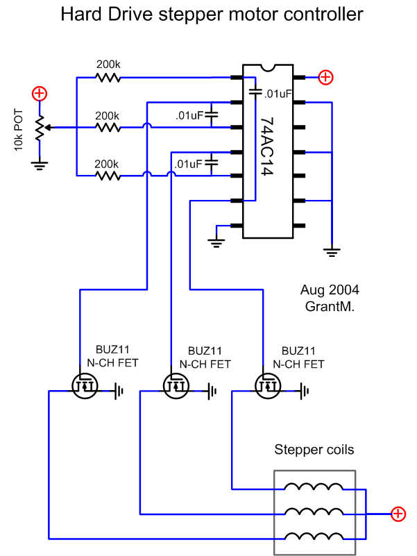
Thanks -
I don't know why but today it worked.... ;D
All of a sudden I reprogrammed the pic once more and it worked perfect!!!
I even build a second pcb and it worked without any problems!
Thank you all!
Here is the pcb of the project!!! -
More dissapointing news ???
Every time I try to program the PIC16F628A I'm using I end up with only the red led to fully work. Blue and Green are working very strange. When I choose the pattern G->GB->B->BR->R->RG-->>G effect there is no light when green and blue should be on.
The only saturated color is red. When I choose the random effect I only get pure red and white (either the red led is on OR all three together).
I have used the Velleman K8048 programmer with the original software (Progpic2 and Picprog2006 both with latest updates) and even IC-PROG.
The PIC is really programmed ok because it verifies ok and when I read back the code the fusses are set correctly.
I can only now pinpoint the fault in the hex program itself.
Any advise? -
Hello again!!!
I've managed to build the pcb and program the pic but there seems to be some problems...
None of the green or blue led seems to be saturated (except the red one) and they don't work as in the project description. There are no random colors and the changing pattern does'nt work. The pcb and the wiring is correct. I only used some bc338 transistors intead of the bc337 described on the project.
I can only pinpoint the problem to bad programming of the pic. Is there any posibility to be programmed wrong using wrong fuses?
When my friend tryied to programme the pic none of the recomended fuses or the oscilator appeared but instead some others did (wich I can't remember). I sugested to change them to the ones the project describes but I get the above malfunctions ???
The problem now is that I can't reprogram them because my friend that owns the pic programmer is out of town:(
You think that using the fuses the binary aks for will solve the problems? -
I ordered 2 leds from Ledsee electronics and I m waiting to get them in my hands. I also wait the pic samples from microchip! Until that moment I hope to have the board ready for soldering!!!
When I get it to work I will try to make some temperature measurements to see if a heatsink is necesery.
And a final question: what settings I must use to Eagle to export the PCB for printing in actual size? -
I want the pcb to be as smaller and compact I can so a regulator with a heatsink is a little "heavy" for me ::) But if I don't find a regulated 5V power supply I will think that option!
This is the next version of the pcb ( including the supply bypass capacitor- no air wires required ;D ).
Any furhter suggestions?
-
I ve only found a 4.5VDC /500mA but I'm not sure I will be able to find one. But I will continue to search in stores here.
-
You show 3.7 ohms but 3.9 ohms is a standard value. It will dissipate a max of 400mW so use a 1/2W or 1W resistor which is larger than what you show.
The 27 ohms will dissipate 250mW so use a 1/2W resistor.
The 15 ohms will dissipate only 100mW so a 1/4W resistor is fine.
I recommend adding a supply bypass capacitor on the pcb even if you must add a jumper for it. Use a 0.1uF ceramic disc.
Thanks for the suggestions.
I will correct the value of the 3.7 ohm resistor to 3.9 as you comment (I'm not very familiar with the available values of components ::) )
As for the capacitor, is ok a 0.1uF / 50V ?
Also do you think the board has space problems using the 1W resistor? I was going to solder them in upright position. -
Thanks. The PCB is not finished yet but when is done I'm gonna upload it for other users! :D
-
Thanks for your answers!
I've decided to "go" with audioguru since he claims that his resistor values are the safer and produce more light that the values described on the project page.
Now I have created a pcb for this project but I'm worry about the routes width. I design it with eagle and I've choose the 0.024 route width (I'm not sure what the unit of this number is).
Is this width enough for 500mA currents or do I need bigger tracks?
Note on pcb:
1) The pic on PCB is the PIC16F83P but it has the same pinout as the PIC16F628A that is not included on Eagle library.
Edit: PCB Image removed. Next version available at next posts! -
Now I'm really confused ???
Reading all these posts I dont really know what resistor values I must use. audioguru had found that the project has problems but no-one confirms that.
What is the most safe resistor values I can use to this project without burning anything?
Thanks!!!

Driving a HDD motor
in Electronic Projects Design/Ideas
Posted
I'm sorry that I have not reply earlyer but I was busy with my work.
I have problems in making the cirquit work.
I 'm testing the circuit in bredboard but it does behave like it should be.
I hear a sound like the motor is spining but in fact is sticked in one position. If I try to rotate it, it moves a little but after a while it stops again.
The measured voltage on mosfets is variable from 0-5V.
I have even try to power the motor with 12V but the result is the same.
By adjusting the 10k pot the "spining sound" changes frequency and I thing the torque of the motor to the oposite direction. Somewhere in the midle I get a smal kick of the motor of trying to get move but it freezes again.
The 4 pins on the back of the HDD are been tried with all the posible position combinations of power and 3 mosfets with the above results in only 2 combinations.
I'm not sure what I'm doing wrong here.
Thanks for the help and your interest!