giroup01
-
Posts
12 -
Joined
-
Last visited
Never
giroup01's Achievements
")
Newbie (1/14)
0
Reputation
-
My 5 year old nephew got the chaser with the green LEDs I bought from a surplus outfit here in Montreal. They're green with clear lens but I'm not sure of the rated mcd. My chaser has red LEDs and they seem a bit dimmer than the green ones, bought bulk without any packaging. The red ones were maybe 10-20 cents a piece, the green ones a tad more expensive. I also gave him my first ever Manhattan project, a little strobe based on the schematic here: tinyurl.com/epw3u and using rather expensive green LEDs, 2 for $3.00 or something close. Now you couldn't operate the thing and look at the LEDs as they would actually hurt your eyes! The next LED project I'm doing will have those expensive green LEDs for sure. All I need now is ...another schematic!
-
Thanks! It's been a fun little project, very well laid out and documented by audioguru. "Totally useless but spectacular" I think he said. I'm returning to electronics after some twenty years and just discovered this 'Manhattan' technique a couple of months ago. In my younger days I used to do my own printed circuit boards but I find that this technique allows me to bring stuff to life much more quickly. And 'in person' the little chaser looks really neat, much better than on the pictures (I'm using a crappy Logitech webcam). I'm no ham guy at all, I don't have a clue about them 20 meter transceivers but I find what they build, and how they build it really fascinating. Lots of cool stuff out there. Thanks for the comments, I appreciate your help and participation, as well as audioguru's and the others in these forums. Pictures from http://www.njqrp.org/qhbextra/8/8c.html
-
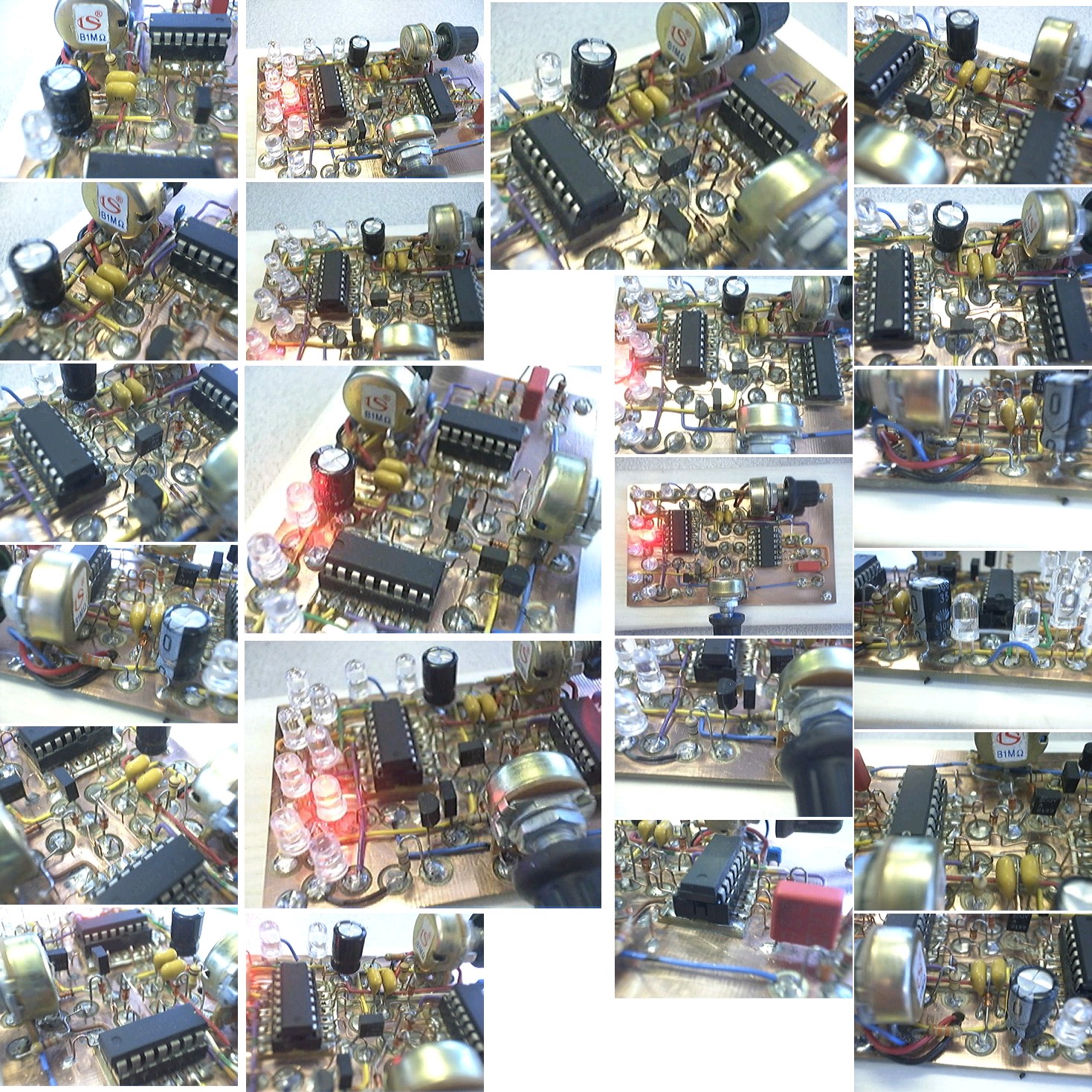
I finally completed my personal 6v LED Chaser, I built a first one that I gave away to my nephew who promply decorated it all over with bright stickers from the dollar store. This one I built for myself and had tremendous fun building it. Originally I wanted to use a support for the LEDs that was smaller in size than the CD used in the project description and have it mounted on a flexible arm attached to the base, so you could aim the LEDs anywhere. I couldn't find anything I could use so I ended up mounting the LEDs on the board in a zigzag sort of way. The board is mounted on a wood base with the batteries hidden under, it looks really good, much better 'in person' than on the (poor quality) pictures. I've attached a few pictures of my completed chaser and a video of the chaser in action. I may eventually mount the LEDs as I originally planned. Next thing I'm building is a 'temperature controller' for my soldering iron, a relay operated off a 555 timer that will switch the thing on and off at preset intervals. Oh sure I could just use a light dimmer but where's the fun in that! [attachment deleted by admin]
-
I've obtained an 'original' Schmitt trigger chip and replaced the NTE sustitute. This has solved the problem as to the flash rate and pause. I'll be getting a few more of these chips as I plan to build a few more of these 6v chasers. The 74HC4017 chip is on backorder. I can't wait to see just how brighter my already bright leds will be! If you have an extra one and want to put it up on eBay I'll buy it right away (I'm in Canada) ;) Thanks for the quick reply to my post and for taking the time to fully document, post and support this cool little project. The second one I'll build will be for me and will have some artistic bend to it too. Stay tuned for pictures! Thanks again!
-
My first project from this board! Works great! Built Manhattan style. Sorry for the poor picture quality though...
-
Hello all, My first post, and my second project from this site (the first one being the transistor tester), returning to electronics after, oh maybe 20 years off. I've built this chaser and with the given component values I'm getting a 10 second pause instead of a 1 second pause, I also had to change C3 and C4 to something like 0.1 uF to get a good 'rotation' speed. (I'm writing this from work and the project is at home so I'm a bit unsure of the values). Anyhow, are the values shown in the parts list accurate? I've ended up using R4 at 1M, R8 at 680R, R9 at 22R, R5 at 10M, C3 and C5 at 330n and C4 at 470n (parts substitution if using a 74C14), the pause is now about 2 seconds. The other changes to the circuit is an NTE subsitute for the Schmitt trigger (NTE4584B) and an 'regular' 4017 an I'm having problems locating a high speed version. All in all I think my little nephew will be quite pleased, and I'm thinking of building one for myself. It's a cool little project. And I remember now why I hate Veroboard so much. Thanks!