zak4000
-
Posts
92 -
Joined
-
Last visited
Never
Content Type
Profiles
Forums
Events
Everything posted by zak4000
-
Download the WinRar from the 'General' forum place, its the one i've got and its the newest one it has no pop-ups...
-
So a 55V+55V 225VA Tranformer with 2x 4700uF Caps. be enough? Would it be ok to swap the MJL21194 and MJL21193 with any of these? http://www.rapidonline.com/productinfo.aspx?id=-1&tier1=Electronic+Components&tier2=Semicon-Discrete+Devices&tier3=MOSFETS&tier4=Audio+FETs&moduleno=67332
-
What current rating should the 6.8uF inductor L1 be? And what V/A should the transformer be?
-
I found out what a ESP file is. For those who don't know what it is, its a picture file that needs to be opened with Abode Illistrator or Coral Draw.
-
Whats a ESP file?? Its in the studio_350w_amp_gevv.rar/studio 350 pcb.zip I'm gussing its some sort of picture... ???
-
I find that this soldering iron gives good solder joints http://www.rapidonline.com/productinfo.aspx?id=-1&tier1=Tools%2c+Fasteners+%26+Production+Equipment&tier2=Soldering+Equipment&tier3=Soldering+Irons&tier4=High+efficiency+25W+soldering+iron+%0dwith+fitted+mains+plug&moduleno=60704 with this solder http://www.rapidonline.com/productinfo.aspx?id=-1&tier1=Tools%2c+Fasteners+%26+Production+Equipment&tier2=Soldering+Equipment&tier3=Solder+%26+Fluxes&tier4=Solder&moduleno=30236
-

how to design very small 6V power supply @100mA
zak4000 replied to nikhil arora's topic in Electronic Projects Design/Ideas
Whats a switching power supply?? ??? -
You could get a ohmmeter and test the leads to see the resistance of them. High= No coil between those 2 tested leads Low (or near low)= Theres a coil between those 2 tested leads
-
Just an update on the design, the dual pot isn't ment to be there - i was getting mixed up with the LM386 that has a veriable gain :-[
-
I'm not shore about a 555 being used but i know another way to make traffic lights... ;)
-
From the datasheet it looks like the TDA2005M and TDA2005S are both the same. They are dual amps - 10W each There are plenty of application configurations for mono and stereo. Hope it helps ;D TDA2005.pdf
-
Hi, i've seen MOSFETs, JFETs, FETs, Diacs and Triacs being used and things but what do Diacs and Triacs do? And whats the difference between MOSFETs, JFETs and FETs from normal transistors??? And how are thay used??? Please explain.... :-\
-
I've designed this using PCB Wizard v2.0, will there be any loop/feedback things?? I havn't mirrored the text yet. :)
-
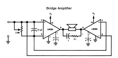
Can someone design a PCB for this schematic?? (The dotted cap. is ment to be a 10uF elec. with a dual pot. in series (one for each amp) for the gain and the 2.5M is the volume) The amp type i'll be using is the LM380N. Thanks LM380_2.5W_Amp..pdf
-
What mobils/networks use what frequances?
-
Does any one know the mobil phone frequances used for the UK??
-
I was experimenting with a subwoofer amp and it suddenly stopped working ??? Any datasheets for a Sound Force QS7889 Version 1.0 sub?
-
Hi i'm looking for a Service/Repair Manual/Schematic for a Goodmans MC100 steoro system.
-
This might help someone..... ;D (updated)
-
So the RMS and peak power across a 6ohm speaker would be: V= Total voltage (subtracting 10V for the transistors + resistors) R= RMS Watts M= RMS Voltage S= Speaker Impedance P= Peak power 2.828= Twice the root of 2 M= V/2.828 R= M*M/S P= R*2 RMS M= 70/2.828 M= 24.75 R= 24.75*24.75/6 R= 102.1W RMS p-to-p P= 102.1*2 P= 204.2W Peak to Peak
-
I googled 'cascode amplifer' and found these things :)..... (the extracted rar is a powerpoint presentation) lecture13.rar Cascode_MOS_Circuit.pdf
-
Thanks :D, but how would you bridge this amp amd how do you work out the RMS and things? :-\
-
Hi, I was just woundering how i could get more power out of my amplifier, i have built the origanal (Orig 100W rms Schematic.JPG) and it works. My 'theory' schematic is 'New Schematic.JPG' - is it right?
-
Thanks rigdoctor! :D