

mixos
-
Posts
581 -
Joined
-
Last visited
Content Type
Profiles
Forums
Events
Posts posted by mixos
-
-
This reverse polarity protection circiut idea was inspired to me by hotwaterwizard. my idea here was to use mainly microwave oven parts, starting with the microwave oven filter circiut, and relays, and i threw in a few diodes and a 1uf 350 volts electro, and a fuse holding circiut board that takes six fuses , and i put in a rotary tap switch, all this ,i put into a home made pvc circiut box, at the front is the switch and input terminal posts and 2 leds, 1 led is power input indicator for 12 volts, the second led is the relay led , this indicates that the relay has come on and is passing 12 volts, now if the inputs were acidently reversed the relay will come on but not pass 12 volts, maybe a few but not 12.
Now the fuses are there to protect the relay wireing in case of short in whatever you power with 12 volts. to simiulate you can short the outputs together and no1 fuse will blow, so by rotateing the rotary switch to the second fuse ill have that to use and it goes up to 3 fuses. the other 3 are spares, now the microwave oven filter circiut, this is an exsperimental idea as its a filter and because i can pass dc iether way through it id thought it may filter any reverse voltage transients from some of my high voltage exsperiments should i decide to link it with one. the microwave oven filter circiut has its own fuse, i deliberately blew that fuse to tap onto the end fuse caps to run it to the other fuses via the rotary switch , ill add more updates when i link this in in some high voltage exsperiments.
by Steven


-
This high voltage bridge rectifier made from microwave oven diodes, i was able to find out the details of these diodes from the net, each is rated at 12kv 550ma so in total thats 48kv
by Steven
-
:) This circiut housed in one of my home made pvc circiut boxes consists of a driver circiut and 12 volts regulator circiut and on the right a modified 12 volts auto ignition coil . the timer for the circiut is at the front pannel pluged into a 555 ic socket fixed to an ic mounting board ,this socket protrude out the front pannel to make replacements simple in case the timer goes faulty.
The 2n3055 npn power transister is at the rear on a heatsink so its easy to replace, like the timer which you only have to unplug it and plug in a new one the modified coil has a new pvc body and the negative input and negative return are rerouted away from the hv positive out of the coil so theres no arcing. the pvc coil body is held in place by a home made pvc coil holder
by Steven
:) This is a multi ignition coil driver circiut with one modified 12 volts auto ignition coil and one unmodified 12 volts auto ignition coil so this has 2 high voltage returns , one at the front and one at the rear
:) This circiut allso housed in a home made pvc circiut box consists, of an ignition coil driver circiut and modified 12 volts auto ignition coil and high voltage trippler, black coloured, and a hiigh voltage modified polarity indicator. the 2n3055 npn transistor at the rear easy to replace and timer at the front just plug it in and this circiut puts out deadly thick looking arcs of electrissity
:) This is another high voltage circiut consists of an ignition coil driver circiut with transistor at the rear and timer at the front pannel for easy access and replacement. allso another type of high voltage trippler and modified 12 volts auto ignition coil the trippler is green and coil black
:) This multi flyback transformer unit contain 2 different types of flyback transformers, one has the hv output and returns both at the top . and can be switched in one at a time for use, the driver circiut is separate and the meter was a 50 volts meter but i use it as a ion wind meter . now this meter only has one wire the other terminal which i have not finished doing is gona be the antanae for high voltage ion wind if ive got it corect so this meter works in what looks like open circiut . its all been tested .
The flyback transformer with the hv output and return at the top is the one that can run through the high voltage pollarity indicator circiut with greater arcs than without and other suprizes


by Steven -
This unit has an ignition coil and flyback driver circiut in the one unit.
by Steven


this ignition coil driver circiut prototype works really good with a 12 volts lead acid cell rechargeble battery. and i was able to power up to 3 ignition coils in parralell with this unit

-
Here we will try to compile a list of high quality electronic sites. Post yours also :D:
http://www.imagineeringezine.com/e-zine/hcircuits.html
http://www.commlinx.com.au/schematics.htm -
This simple looking circiut i modified to run off the high voltage output of one out of 2 high voltage output flyback transformers in a multiflyback driver circiut i biult, the leds work perfect no burnouts and by adjusting the driver circiut i get one led come on telling me its high voltage dc, with some more adjustments i get 2 leds come on telling me its now high voltage ac, 2 of the wires dont touch, as one is an antanae and the other hv out, i found not only increased arcs but plenty blue , leaveing me to ponder if this would be a good lifter power source like used in the j naudin lifter sites on the net so ill be conducting more tests.
by Steven
-
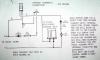
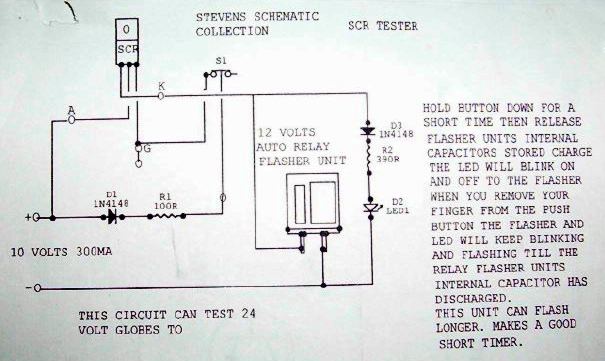
This simple scr testor uses very few components but the main one is the 12 volts auto indicator flasher unit from a car. of which is what flashers your indicators, the socket to plug the scr into you can make by breaking down a large intergrated circiut socket, into a length that has 3 sockets for a 3 legged component .
You will get the idea by viewing the n channel mosfet testor of which the ic socket section for plugging the mosfet into has 4 sections insteatd of 3, but you only use 3. the extra one . disregard. it now3 this scr testor allso ,as i found out recently has a few good uses. and one is a reverse mode transformer testor , which puts out 2 pulses from a 12 volts input, one is the steped up voltage from the transformer the second is the kickback pulse from the indicator flasher units internal coil or relay coil.
by Steven
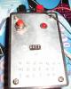
This simple scr testor , has some good uses and i used it to pulse test a transformer in reverse mode i got one good shock from the transformer and a small one followed , i beleave was the kickback pulse from the flasher units coil in the picture you see the scr plugged into a cut down ic socket, of which i used as an scr plug . just push the button for a short time to test the scr ,and once the relay activates and the led blinks on and off till the internal capacitor in the flasher units charge is drained . but as long as the relay activates and the led blinks you can still be asure the scr is working ok , as its part of the circiut.


-
Heats fast, cools fast
The Cold Heat Soldering Tool is a cordless tool that heats quickly and cools down nearly as fast. It creates the heat right in the proprietary tip material, making the tool 20 times more efficient than the average conventional soldering iron. The tip reaches 500 F in less than 1 second for many types of joints and cools to the touch in 1-5 seconds so you can put it away -
This simple mosfet tester ill email you what it looks like as a unit simple and effective if you have any trouble seeing it let me know ill redo a highlighted version. by Steven

-
Steven writes:This schematic is what my flyback driver circiut is from just remove the transformer section and the rest and throw in a flyback transformer. because you can power them easy and still allso use a transformer in reverse mode for arcs to like the flyback transformer arcs

-
Here comes more photos:


-
Steven writes:With all the odd size flyback transformers around its handy to have a pvc suport. first youll need a pvc pipe the size i used in pvc circiut box designing featured in the electronics lab , now cut a peace of pipe the length of the flyback transformer .
Cut it down one side, and if you dont have a home made cutting gig just use a ruller and draw a straight line then use a mini dril and drill a doted line of holes down that strait line, then splice it open with a stanley knife or box cutter. then pry it open with your fingers , and hold it over the stove flame until its soft enougth to open out more and flatten under your shoes, on the floor.
Then cut out the rectangle size you need make it reasonably long , and no wider than the length of the flyback transformers body . useing a pair of long nose pliers hold that pvc you cut out over the stove flame till its soft enougth then with a pair of gloves on hold it over the flyback transformer core side and while the pvc is still soft bend it to the shape as shown in the pictures and bend out the ends to form legs for this suport.
Then useing a file round off the corners and drill the holes, for the screws. glue the flyback to this pvc holder suport. you can use a bit of blue tac which you can allso get yellow ,to fill in any gaps.


-
Inside Transformers
http://www.du.edu/~jcalvert/tech/transfor.htm
Transformer Basics
http://www.federalpacific.com/university/transbasics/transbasics.html -
The best way to print it out correctly is to make some test prints to find the correct ratio. Take a part with fixed dimensions (like an IC) and try to fit it on the print out paper. Then change accordingly the ratio (resize scale) to achieve the correct dimensions. It is better to use a program that allows you to change the percentage (%) of the print out.
-
Members rated depending the messages they write.
0-50 posts: Newbie
over 50 posts: Jr. Member
over 100 posts: Full Member
over 250 posts: Sr. Member
over 500 posts: Electronics God -
The best way to print it out correctly is to make some test prints to find the correct ratio. Take a part with fixed dimensions and try to fit on the print out paper. Then change accordingly the ratio to achieve the correct dimensions. It is better to use a program that allow you to change the percentage (%) of the print out and not the ratio.
I don't know another more "easy" way to print a PCB from an image file. -
Here is also a related topic:
http://www.electronics-lab.com/forum/index.php?board=13;action=display;threadid=370;start=msg1463#msg1463 -
Here are two files related to ISL3871. These are not the datasheets but may help.
-
Hello SicMan
I created a Sell/Buy category. Check it here:
http://www.electronics-lab.com/forum/index.php?board=25
You can freelly post your "goods" there including price, photos, description etc. Please take care to make your listings as clear as you can to maintain the quality of our forum.
If you have any question, don't hesitate to contact me. -
Things are easy, don't be confuzed. ;)
When you have +/-15V and ground (0V) that means that if you measure across ground and +15 you will get +15V reading and if you measure across ground and -15 you will get -15V reading if you don't move the test probe that was to the ground. These are called symmetrical voltages.
If you measure across the +15V and -15V you will get a 30V reading.
Take a look at the schematic I attach. It is a symmetrical power supply that is suitable for powering your opamp if you don't have a +/-15V PSU.
To wire the opamp, put the +/-15V at the corresponding pins and take the output related to the groung (0V) of your power supply.
You can also attach your schematic here.
-
Also here :
http://www.electronic-circuits-diagrams.com/audioimages/audiockt11.shtml
you will find a simple use of DS1669 digital potentiometer. The same circuit is here also :
http://www.electronics-lab.com/projects/audio/033/
-
Sorry my friend, i thought it was ::)
-
I attach you the LAG668 Datasheet
-
Here it is:
http://www-us16.semiconductors.com/acrobat/datasheets/PCF50732_2.pdf


Led display Digital Voltmeter question
in Projects Q/A
Posted
I came across a Digital Thermometer that used ICL7107 and it had a subcircuit to easilly produce the -5V that ICL7107 needs. I post it here:
