

mixos
-
Posts
581 -
Joined
-
Last visited
Content Type
Profiles
Forums
Events
Posts posted by mixos
-
-
Here is what i found:
SS495A Datasheet 1
SS495A Datasheet 2
There are not the same. Download them both.
Where are you gonna use this sensor? I am just curious ;D -

Even on the advanced spacecraft of the future, sooner or later things are bound to break. Space travelers on an extended mission to Mars, for example, would need to be ready to do small repairs just in case, soldering this, welding that ... more here:
http://science.nasa.gov/headlines/y2003/10nov_solder.htm?list875305 -
Number 2: Already done
I added a "more recent topics" link under the recent topics at the front page.
Number 1: Sometime in future i will do that. -
A new board created at the online Electronics Lab community :D
Name: Circuit/General Requests
Description: This is the ideal board to request projects, circuits, pages translations or anything else.
Some posts from other places that requesting something will be moved here. -
Hello
Here it is: http://www.electronics-lab.com/projects/pc/012/index.html
Hope you like it :D ! -
Hello
Go here: http://electronickits.com/start.html?BID=1799&AID=11540
and check: POWER SUPPLIES -> DC Bench Power Supply Kit
Output Voltage:
1) 1.5VDC - 15VDC @ 1Amp
2) -1.5VDC to -15VDC
3) 5VDC @ 3 Amps
Input: 110VAC (line cord included).
Includes full enclosure and knobs
Features short circuit protection on all supplies
Variable outputs can be stacked to get 3-30VDC @ 1Amp
Price : 54.95$ (as kit) or 89.95$ (assembled) -
Great!! :D
Can u post here the exact circuit so we can see it and help you? -
Charasteristics:
2N2222
FEATURES -
Hello flood
I translated this for you.
You can find it here: http://www.electronics-lab.com/projects/misc/002/index.html
Hope you like it ;)
Mike -
Copy-paste from TL081 datasheet:
"The TL081 is pin compatible with the standard LM741 and uses the same offset voltage adjustment circuitry. This feature allows designers to immediately upgrade the overall performance of existing LM741 designs."
Replacing TL081 with LM741 may drop the overall performance and quality of the power supply, but it will work as they are compatible. Otherwise TL081 is a very common opamp, so try to search it a little more.. it worths to do it.
Don't forget to send feedback when you build it! -
What screen resolution are you using? Is www.Electronics-Lab.com design resolution makes your life hard?
-
Here is BJT Transistor Review I found:
http://www.electronics-lab.com/articles/files/BJT_Transistor_Review.doc
More electronics articles here: http://www.electronics-lab.com/articles/index.html -
I attach some circuits on how to use 723 in positive and negative regulation. Hope that helps.
More info in datasheet: Download LM723 Datasheet
-
Hello Electronicslady.
Welcome to Electronics-Lab community :)
Pins 10,11,16 connect together and to the rest of the circuit.
Pins 3-9,13 (3,4,5,6,7,8,9,13) connect together and to the rest of the circuit. -
I translated it in English for you.. you can find it here:
http://www.electronics-lab.com/projects/telephone/001/index_en.html
But you could build it just by using the schematic, pcb and parts list. There is no special info in text. -
Here : http://xoscope.sourceforge.net/ you can find a very good Linux based oscilloscope.
-
1. I think the connection is ok. There is no need to use a feedback loop in every opamp. There are many types of connections that can be used with opamps.
2. A Bi-color LED is a led that lights two colors. There are two types: with three or two leads. Here you need one with 2 leads. When the current flows in one direction the led lights the first color and when the currents reverses the second color lights.
3. Insert in the female jack (connected to circuit) a male jack and with a contuinity tester (ohmmeter at lowest scale) measure the leads to see which one of the male jack connects with the females one. When this clears out.. you can connect the correct leads to the circuit so if you insert a ear phone it is connected to the circuit. You don't have to care much about polatiry.
You may use a speaker if the amplification is sufficient. Just give it a try.
When you finish it .. tell as your experiences here.. -
You are welcome Vedran, don't be shame :)
At the + - 12v points appears such a voltage if your power supply work ok. You don't need to connect anything if you plug at the Power Socket the output of a power transformer of 12V.
Otherwise if you don't connect a tranformer and you have a power supply of 12V that don't need a rectifier (has already) you can connect it at + - 12V points without connecting nothing to the Power Socket.
I other words this is to alternative power the circuit from an already rectified source. Also you can take the + -12V from there if you want to use them somewhere else and the amperage is sufficient. -
There must be a typographical error about 1N4004. It's place is where 1N4001 is on pcb. In other words on pcb 1N4001 -> 1N4004.
The 0.01uF capacitor is near 7812, the green one. It's a tantalium or ceramic one. Nothing special.
The 1A Bridge Rectifier is nothing special either. It's just a plain 1A Bridge Rectifier like below:
The botton one fits better in pcb.
I am sorry, but there are not schematics available.
I attach you the part that you don't understand. Is it clear now?
-
The transistors are general purpose PNP transistors.
You can use:
BC556 or BC557 --> Download Datasheet -
Hello :D
You can find some Soundcard oscilloscopes software that require no hardware to be attached to the pc. You need only one sound card and some connectors to drive the signal at the input of the sound card of your pc.
Check here: http://www.electronics-lab.com/downloads/pc/index.html
Additional pc oscilloscopes:
Non Commercial
http://www.ee.washington.edu/conselec/CE/sp95reports/guterman/final/scope1.htm
http://www.geocities.com/huz_52/
http://home.planet.nl/~m.f.hajer/
http://www.discovercircuits.com/O/oscilloscopes.htm
http://www.geocities.com/tangmonster911/oscilloscope.htm (ISA bus)
http://www.dansworkshop.com/Homebuilt%20oscilloscope.shtml (TV based)
http://www.geocities.com/SiliconValley/Lakes/7156/articl3.htm (with LEDs)
http://www.electronic-projects.net/Electronic-Projects/projects/telescope/index.shtml (TV based)
http://www.intio.or.jp/jf10zl/tvosc.htm (TV based)
Commercial:
http://www.qkits.com/serv/qkits/velleman/pages/pcs500.asp
http://www.scope4pc.com/
http://www.acqiris.com/Products/Cougar_main.html
http://www.picotech.com/oscilloscope.html
http://www.designnotes.com/Specials0702.htm
http://www.usb-instruments.com/ (USB)
http://www.arborsci.com/Products_Pages/Software/PCOscilloscope.asp
http://www.linkinstruments.com/oscilloscope21.htm
http://www.bitscope.com/ -
Ever wondered what's inside your monitor? Here are some pictures from a broken monitor CRT that helps you clear out the mystery.
Remember: Don't try it yourself because may be dangerous..JPG)
The tube broken... and we are ready to see inside..JPG)
Ops... I thought it was empty :o ! I was wrong..JPG)
There is a metal housing there. It is used to cage the electrons inside it..JPG)
:o There is a "rainbow" inside!! Why? Because the front screen has tiny dots that act like a diffraction pattern for the light and analyse it to the spectrum..JPG)
Let's see it more closely..JPG)
And from another point of view!.JPG)
Ohh.. I forgot the most important thing! The electon gun!.JPG)
No, it's not so big... it's the little silver thing at the center..JPG)
But electron gun isn't alone.. Has some coils around it..JPG)
They are cooperating at high speed to produce a nice image.
Now the cooperation finishes.... The electron gun separated from it's company.. and it's time to follow it's own carier!
Also see Shooting a CRT: http://entertainment.howstuffworks.com/what-if-shoot-tv.htm -
Hello Junkman
Thanks for your interesting description.. it's really interesting (and dangerous :o) to "play" with power electronics! Have you got any photo of your charger? It will be very interesting also. What type of batteries you charge with it?
I propose to make a portable electric winding machine using those high amperage diodes. But you must find a high amperage transformer also! Not easy e?
Electronic junks are not junks for an electronic man! -
As manotronic noticed you can use a 555 timer in Monostable mode:
The basic circuit is this: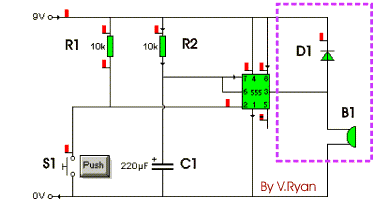
For circuit description and how to attach a relay visit: http://www.technologystudent.com/elec1/5554.htm


Led display Digital Voltmeter question
in Projects Q/A
Posted
If you ground -5V pin, and apply +5V to the pin 3 then it will work nice :D for measuring positive voltages (i already tried it). I am not sure what will happen with negative voltages, i haven't tried it.
Hope that helps a bit.