mixos
-
Posts
581 -
Joined
-
Last visited
Content Type
Profiles
Forums
Events
Everything posted by mixos
-
Has anyone seen any fatal error the last day? I didn't see any.
-
In these pictures i used a small elctronic circuit box to install the microwave oven moter/ generator into. first i had to cut and file a tryangle hole in it so that the plastic part of the generator with the terminals sticking out ,will protrude through. then i drilled the holes and inserted 2 bolts to keep the moter in place, after i a drilled the hole for the plastic generator shaft to go through, then i made the back cover from a peace of flattend pvc pipe, the same i used to design my circuit boxes with, then i inserted the square white turn peace that slips onto the shaft. Then i drilled a small hole through, the center and put a screw in to secure the turn peace to the plastic generator shaft., although the turn peace fits over the shaft ok ,its a bit hard to hold it to crank up the generator so ill make a wheel for it. by Steven
-
;) You are welcome Ante! Thanks for your support to this site. You give life to it! :D
-
Anyone needs a 8-SOIC to DIP adapter? Here is one used to connect a AT45DB041B memory to breadboard.
-
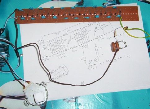
in this setup are 2x 6kv 0.0022uf ceraimcs solder together in parralell with only 1x 1m 1/2 watt resistor, this mini marx setup works good and runs off the high voltage multiplier circuit which is powerd up by rotateing the microwave oven motor generator, so in this exsperiment it wsent nessisary to use higher value resistors on the other side of the ceramics as im not runing it off the hv output of a flyback transformer, the total voltage rateing is 12kv , every few rotations of the generator outputs a fast fat arc between the spark gaps , before this test i had another setup 3x2kv ceramics in parralell at 0.01uf each and when i rotated the generator, nothing happend untill i put the generator down then reached over towards the hv ceramics with my finger and i wasent cloe enougth to it when it fired off by itself , like a delayed arc that was fast and loud by Steven Here is a closeup of the exsperimental mini marx setup used in the output of the voltage multiplier circuit powerd by the microwave oven motor generator
-
I made another change. Now seems that error gone. Please report here if you see this fatal error again. Thanks for your help
-
I made a small change. Please report here if you see again this error message: Fatal error: Cannot redeclare phpadmentor_maxinttonull() (previously declared in /home/electronics-lab.com/www/advertising/phpadmentor_config.php:18) in /home/electronics-lab.com/www/advertising/phpadmentor_config.php on line 18
-
ok, hotwaterwizard. I increased the allowed attachment filesize to 3000KB. Hope this help you continue posting the datasheets you found. But, please if the datasheet is already in a web site, post a link to it and don't upload the datasheet here if it's to big.
-
This circuit from my circuit collection is an intresting circuit to biuld ,ive tested this out some time ago and beleave it may have some handy uses. by Steven (received via e-mail)
-
The site moved on a new server located in USA, that
-
There is a paint spray out there: Testors #1601 Transparent Candy Emerald Green - Spray Enamel That's it's great for PCB coating paint. Can be found here: http://www.a2zhobbies.com/Testors/Hobby_Sprays/TES-1601.html http://www.endlesshobbies.com http://www.discount-train.com/models/testors/testors_7.html I am still searching an e-shop in Europe to buy it online, because they don't ship it outside US.
-
I am aware of all the problems that you mention. I am trying to do my best to keep the site up and running.
-
During the retest of the simple modified high voltage polarity indicator, which apears to really make the high voltage arcs stronger and shoot further, the test i did in darker conditions seem to come up better in showing the arcs and the 2 lit leds when i think it should of been one, dureing the spectacular lightening storm on my desk, yes my desk as i failed to remember to get rid of the conductive contact paper covering my desk. and holding a camera and switching it on and trying to adjust the driver at the same time , and use whatever i can to hold 2 wires in position , but anyhow i used a peace of pvc pipe to hold the wire on with blue tac but some how dureing the photographing the pvc pipe rolled apart and i couldent beleave my eyes to see this really long purple arc shoot that far , with the hv optimizer circuit, it certainly gave the arcs greater distance, like a marx generator but in all the rush in trying to photograph it i ended up getting the photo wrong , but anyhow in the darker photo that came out the best, youll see the 2 leds lit up, the other darker photos taken to show the arcs better came out blury , remember i was doing to many things at the same time and in the middle of a lightening storm, the best insulated wire from the driver circuit to the flyback was arcing to the desk top conductive paper and other parts to untill i resolved it, the really longest arc when i tried to photograph it i messed up as got the wrong thing in the picture ,in the rush.
-
In these 2 pictures retesting this simple modified circuit, to give led indication of hv arc flow from one wire to the other , was delayed by the 12 volts battery powering the flyback driver circuit,runing low on voltage. the arcs were so thin you wont see them let alone the red led lighting up, so ill redo the test when the battery is fully charged, the red when lite indicates hv dc , next test ill do it in a slightly darker condition , so you can see the red led lit up. this circuit is only the second out of 2. by Steven (received via e-mail)
-
Topic unlocked. Please continue the comments on this and how to make it work.
-
How often do you see those messages? Last days i see some connection problems also.. assuming that are caused due to the recent tranfer of my hosting company. Hope these to eliminate in near future.
-
Dismantled view of a 6 to 96 led light chasser display In these pictures of one of 3 led chasers, i dismantled to salvage the needed prototype boards in one picture shows the long led mounting board with the small holes down the centre, which the small leds fit perfectly this long board is only one of 2 boards used the main board has the 555ic and electro and decade counter, this decade counter indentation ,that s supposed to mark the top left number 1 pin, is at the opposite end of the chip, making it look like its upside down, when its not, on the main board you
-
This redrawn simplfied circiut from my collection was drawn ina special way by circiut maker and retraced in black to highlight it enougth to come out when photographed, for posting, ill post another similiar one soon and because it uses more of the 4017 decade counter pins, it allso makes a good decade counter testor. by Steven (received via e-mail)
-
This light chasser , i used to power 96 leds and used it as a lotto number picker , by tapping to each side of the electro. and runing the wires to a push button switch ,enabled me to create a short when the button is pushed, this stops the leds in there tracks . where the numbers for the lotto was below each led . this was tried with the other light chasser. but may still work the same with this.the other version had a 105 poly in place of the electro and allso had a logic ic instead of the timer. so ill post that one next time. by Steven (received via e-mail)
-
This circuit i build from a kit , that i brought some time ago from dicksmiths electronics, really has it uses the circuit may work by shorting out the leds, so some one tells me, and so i posted this for all to share. by Steven (received via e-mail)
-
That's ok Ante, but be more careful next time! We still love you :P!
-
 Coil levitation device and electromagnetic launcher circuits by Steven (received via e-mail)
 -
These 7400 ic testors i biult in 2 sections to make biulding them easyer , just add a push button and plug the 7400 ic into the socket and push the button to test, leds will alternate to indicate that the first section is working ok . to test the other section just plug the 7400 ic into the socket in the other circiut to teast the 2nd half of it , note the simplicity of the 2 section 7400 ic testor . by Steven (received via e-mail)
-
In these 2 circiuts the components are the same as that of the 741 ic testor except that they test each 741 ic out of 2 , in the 1458 ic chip , the wireing to each ic socket where the 1458 ic plugs into is the only different thing, youll notice , apart from the location of one push button and slide switch, and the error writeing at top identifying them both as tester one and one when its meant to be 1 and 2 plug the 1458 ic into the first socket , then slide the switch on. one led will come on, then slide the switch off and push the button, the second led will come on, indicateing the first 741ic in the 1458 ic chip to be working ok . Then plug the 1458 ic into the second socket and repeat the testing procedure to test the second 741 ic in that 1458 ic. the same testing proceedure aplies to the 741 ic testor by Steven (received via e-mail)
-
Please don't post unusefull messages! Here is not a chat room but a forum to express yourself circumstantial ! Help us to maintain this forum clear and in a high quality state. Note that unusefull messages will be deleted with not a prior notification to maintain the database clear. Hope to understand this!