bob_s
-
Posts
20 -
Joined
-
Last visited
Never
Content Type
Profiles
Forums
Events
Everything posted by bob_s
-
MP, Here is some more data that you might be interested in. It has to do with power dissipation of the KTP package I'm using. The one inch square pcb copper improves the power dissipation greatly if done correctly. Take a look at page 6, I'm using a pattern similar to #4. If the power dissipation is calculated as (Tj - Ta)/Ja = (125C - 25C)/(25.8C/W) = 3.876W which is more than double what I need. I would like it if the package was cooler but it is well within it's operating parameters. The issue of input voltage was defined at the start, I'm using 12v. I did't see the purpose in dropping the voltage down just to regulate it down once more. Bob Power_Flex_KTP.pdf
-
Sorry MP, I have to disagree with you. I know from experience that this regulator will not work well with less than 8v. This is why my previous circuit provided 8v for it to regulate properly. With any less the regulator was not consistent. Besides the problem was I needed 12v for my circuit not 8v. After adding the filtering caps the regulator ran well within the acceptable limits. Thanks for your input though. Bob
-
MP, Thanks for the reply. However the problem has been solved (except for the imperial/metric problem :)) The regulator had gone into oscillation and required some filtering. Bob
-
audioguru, The temp is 126F which is about 52C which works out to 52C/28C = 1.85W. That's pretty close to what we were looking for. Sorry about the confusion with the temperature unit. Thanks again. Bob
-
audioguru, Thanks, you were right. It did need both 0.33uf and 0.1uf cap. Brought the temp down to 126 and stable. It must have been oscillatint. Thanks also for correcting me in my calculation. I'll try to remember that for next time. Bob
-
I've been trying to power an LCD module using a UA78M05CKTPR regulator (power-flex package) but the regulator gets very hot. I measured it with a temperature probe and its more than 155F which is too high. The max operating temp is 150F and the recommended operating temp is 125F. The LCD LED backlight requires 5v at 210ma and I also 5 other LED's (10ma each). I am supplying the regulator with a regulated 12v. I thought at 250ma a heat sink would not be required as it only needs to dissipate 3 watts of power, 12v x 250ma = 3W (although I have soldered it on a 1 inch square on an FR4 0.062" copper PCB) . I had this same circuit working just fine when I powered it with an unregulated 8v at 2 watts of power but I needed the 12v for another addition to the circuit. I have two other regulators off of the same 12v. One at 5v (50ma) and the other at 3.3v (100ma) and neither of them even get warm. So why would the extra 4v cause such a problem? I've attached the datasheet for the regulator. Thanks for any help. Bob UA78M00_Series.pdf
-
This seems to be an impossible task. Trying to adjust for the wide range of CTR, loss of LED integrity and temperature changes. I seems to me that tranfering the information is still best done digitally and then converting it to an analog signal or a timed digital signal on the other side. So I've decided to add a small micro (12F675) to supervise the circuit and send the data digitally. Thanks for all your help. I've learned alot from your comments and suggestions. Bob
-
Ok that's sounds great! But how do I make an adjustable gain op amp circuit? Bob
-
Audioguru, I've found from experience that the motor requires an inrush of full current for at least 10ms to get started. I'll have to wait for the spec sheet on the motor until monday. I've managed to free up an analog channel for the sensing circuit and I am planning on using it to check the sensing circuit once every 100ms. You said that the circuit you changed would output 3.03v if R2 was 910k, that works for me. I've wanted to get an optocoupler to work in it's linear range but could not figure it out. How do I get the output to follow the input? Bob
-
Ok. Then the output is not a digital signal but rather an averaged DC output. This is not exactly what I was looking for. I only have a digital input available. Could I expect a cleaner signal if the drive signal was 20khz (50us)? Bob
-
Wow! Thanks you guys for all the help your giving me. I have a question in regards to frequency. I am driving the fet at 50khz and somewhere between 25 and 100% duty. I am using a PS2501 optocoupler. What kind of delay can I expect from input pulse to opto output? Bob
-
Ante, I've been busy dealing with another issue and have not been able to try this circuit out yet. Could you explain the theory of this circuit to me? Why you chose the values? What was your train of thought? I would like to understand the theory better before using this circuit. Thanks
-
Ok. So how do I set up the circuit? I am not that familiar with opamp circuits. Bob
-
I wouldn't want to have more than 1V drop. Less is better.
-
I already have motion feedback. Having current feedback as well gives me a better indication of what is happening (limit switch, obstruction, etc..).
-
I'm sorry. What I meant to say is that the motor does require a minimum amount of drive in order to move with it's load and that works out to about 1A or more of current flow. I need this motor to move very slow in some circumstances. I would like to have the feedback that you just described. But I am limited to one digital input to my controller circuit. I am using a PIC microcontroller and have an EXT interrupt pin available that I can use to count pulses, etc... At this point I would be happy with just a "yes" it's flowing or "no" it's not. These motors have physical limit switches which open and introduce reverse bias diodes interupting current flow and this is what I need to know is happening. The current stops at the limit and will only flow in the opposite direction until the switch closes again shorting out the diode. One thought that I had was to use a pair of op-amps. Feading the voltage of a small current sense resistor (0.1ohm) into the first amplifier (unity gain) and then an inverting amplifier (x10 ) to turn the opto isolator on. I am just not sure how to set this circuit up.
-
I'm not interested in the amount of current flowing but rather that it is flowing. The schematic only shows a portion of my circuit. It does already have current limiting. However, I only have a digital input available to use in my sensor circuit. I believe the stall current for this motor is about 1A. So if the opto is turned on when the current is greater than 1A that would be great.
-
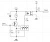
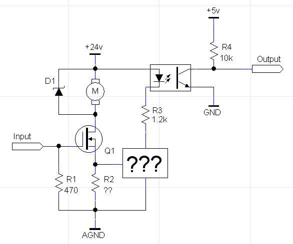
I have a motor circuit which needs to have feedback for current flow through the motor (see attachment). The input drive is pulse width modulated at 50khz. The motor draws up to 6A. How do I get the optoisolator to turn on when current flows?