

kumaran
-
Posts
51 -
Joined
-
Last visited
Never
Content Type
Profiles
Forums
Events
Everything posted by kumaran
-
Hi Guys, You can only be understand if you are experimenting it. Back to basic. Energy cannot be created. Just transformation. It's true in this type of devices. Lutec motor, adams motor(1970's), bedini motor earlier versions are using mechanical switching. But now they changed to solid state switching. Power extraction method is the key to gain more power compare to input. Just using transformer can gain more power compared to input (resonance). As I say, join [email protected] or [email protected] to learn more. Just read those postings and ask questions in the group. I'm diverting you from here but if those need more information on these devices, then join the groups. The main recent I was here is to learn electronics which can help me in this project. Going through so many projects in this site does help me in my project.
-
Almost forgot about this side. I was testing so many motors and theories for the past 1 year and as of right now just got about 1:1 ratio. Not easy but possibilities are there. I'm very active members in [email protected]. All my findings and testing results posted there. Anybody interested in free energy device, just join the group and learn.
-
Battery is a must in order to retain self running for this type of motor. Have your read those links I have posted? Osiloscope doesn't lie. He has feedback output current into drive battery. The output current is more than input current. In this case the battery will never dry out while running motor. Think of conventional motor compared to this motors. What is the different? Simple, when normal DC motor runs, drive battery depletes. But for OU motor, the drive battery doesn't deplete yet powers the motor. It means the motor will run forever. I was sceptic as you were before but I took sometime to do hands on experiment then only I realise that there are chances to gain free energy. I'm not scientise to theorise the fenomena at this moment. If you really have interest just join yahoo group [EVGRAY] and read through those postings. There are people in that group who achived OU (Overunity) results. Yet they still experimenting other parameters to get maximum output. I think it is better for me to not argue on this matter. I will post matters that related to electronics only. But as I promised, once I have completed my projects, I will publish those result on the web. Period. Sorry if I have heard some of you.
-
Hi all, People has achived self running motor. http://peswiki.com/index.php/Directory:Bedini_SG:Replications:Marcus:Self-Running
-
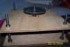
Sorry the attachment missing. Here is the photo.
-
Finally the motor frame with rotor contructed. The rotor is not shown in the picture (in between two plywood). The top plate will be used as timing disk. This motor I would consider the best design I built so far. Still pending on stator windings. Will update the progress. No worries.
-
Special thanks to you Yevgeni for the circuit diagram. I appreciate it. Thanks. :-*
-
Hi, Thanks for the feedbacks. OK yesterday I'm able to make this reflective optoswitch work by adding some resistor. Take a look at the circuit diagram. Now it reacts as I wanted it to be. Sorry, I not expert in drawing. Any comments or feedback to make the circuit better?
-
Thanks Yevgeni, I have tested this circuit. In the place of coil I have place electronic beeper. I noticed that even any material I bring near to optoswitch, the sensor detects it and beeper starts beeping. Nearer the object to opto, louder the noise. How to prevent this from happening? Do I need to place resistors anywhere in the circuit? I just need the switch to turn on when it detects reflective material. Other than that swith should turn off. I'm using 5V for IR and 12V for sensor. Ante, look at the optoswitch datasheet attached. I'm using model QRB1134. Please suggest QRB1133.pdf
-
Hi, Waiting for your answers? Anyone knows what I want? Please reply to my post. Thank you.
-
Hi experts, Need your assistance right now. I have bought some reflective optoswithes for the project. Attached is the datasheet for optoswitch. Let me tell you what I want to do with these switches. I will place some relective material on top of the rotor. When optoswitch sense this material the switch will turn on then stator push the magnet away and rotor turns. I need this switch to trigger 2N3055 transistor. Stator coil is connected to 2N3055. Is there any other method to use? Optoswitch -> 2N3055 -> Stator Coil. ::) Do I need to use opamp before transistor? ??? Can anyone draw the schematic diagram for this setup? QRB1113.pdf
-
Ante & all, After seeing the circuit setup, and some result statistic, anyone has some suggestions on recapture the back EMF from drive and trigger coil into batteries? Any suggestion on component to replace to make more efficient? Looking forward for an answer. Please get back to me...
-
I wish I had tachometer to measure the RPM and equipments to test motor torque. So those RPM result is based from observation and by analyzing sound created while motor spins fast or slow (unreliable). Is there any way to get or make cheaper tachometer. Will do more testing by adding generator coils.
-
Ante, Hope I could find some. By the way go to "Adams Motor Project" and read some newest discoveries I add.
-
Hi everybody, I did some test run with minimal modification on coils and resistor. Read specification below. Test setup Circuit Used the same circuit as previous test run. No changes except trigger resistor and swaping trigger coil with drive coil. Battery Battery A : 12V 7AH Gel Cell Battery B : 12V 4AH Lead Asid Battery C : 12V 4AH Lead Asid Coils Trigger coil : #23 (Bigger) Drive coil : #26 (Smaller) Generator coil : #23 (Bigger) Resistor 2K ohm A-meter connected from battery terminal to circuit. Test Result [table] [tr] [td] Time [/td] [td] Batt A [/td] [td] Batt B [/td] [td] Batt C [/td] [td] Input Amp [/td] [td] Remark [/td] [/tr] [tr] [td] 22.50 [/td] [td] 12.70 [/td] [td] 12.27 [/td] [td] 12.17 [/td] [td] 0.19 [/td] [td]Motor starts up normally. The amp reduces until 0.19. Motor RPM at maximum.[/td] [/tr] [tr] [td] 22.55 [/td] [td] 12.70 [/td] [td] 12.27 [/td] [td] 12.20 [/td] [td] 0.18 [/td] [td]Amp drops but RPM increased. Notice batt C voltage increase to 12.20. :o Probably motor run at resonance stage right now.[/td] [/tr] [tr] [td] 23.00 [/td] [td] 12.70 [/td] [td] 12.27 [/td] [td] 12.20 [/td] [td] 0.18 [/td] [td][/td] [/tr] [tr] [td] 23.05 [/td] [td] 12.69 [/td] [td] 12.27 [/td] [td] 12.19 [/td] [td] 0.18 [/td] [td][/td] [/tr] [tr] [td] 23.10 [/td] [td] 12.69 [/td] [td] 12.26 [/td] [td] 12.19 [/td] [td] 0.18 [/td] [td][/td] [/tr] [tr] [td] 23.15 [/td] [td] 12.68 [/td] [td] 12.26 [/td] [td] 12.19 [/td] [td] 0.18 [/td] [td][/td] [/tr] [tr] [td] 23.20 [/td] [td] 12.68 [/td] [td] 12.26 [/td] [td] 12.18 [/td] [td] 0.18 [/td] [td][/td] [/tr] [tr] [td] 23.25 [/td] [td] 12.68 [/td] [td] 12.26 [/td] [td] 12.18 [/td] [td] 0.17 [/td] [td]Notice the amp drops to 0.17. RPM drops a bit.[/td] [/tr] [tr] [td] 23.30 [/td] [td] 12.67 [/td] [td] 12.25 [/td] [td] 12.17 [/td] [td] 0.17 [/td] [td][/td] [/tr] [tr] [td] 23.35 [/td] [td] 12.67 [/td] [td] 12.25 [/td] [td] 12.17 [/td] [td] 0.17 [/td] [td][/td] [/tr] [tr] [td] 23.40 [/td] [td] 12.67 [/td] [td] 12.25 [/td] [td] 12.17 [/td] [td] 0.17 [/td] [td][/td] [/tr] [tr] [td] 23.45 [/td] [td] 12.67 [/td] [td] 12.24 [/td] [td] 12.16 [/td] [td] 0.17 [/td] [td][/td] [/tr] [tr] [td] 23.50 [/td] [td] 12.66 [/td] [td] 12.24 [/td] [td] 12.16 [/td] [td] 0.17 [/td] [td]Last reading taken before go to get some sleep. Let the motor run overnight.[/td] [/tr] [tr] [td] 07.55 [/td] [td] 12.35 [/td] [td] 11.88 [/td] [td] 11.69 [/td] [td] 0.16 [/td] [td]Last reading taken before stop the motor. Notice the amp gone down to 0.16 and RPM decreased a little bit.[/td] [/tr] [/table] Test Explaination I have notice that the motor runs more efficiently compare to previous test run. Low input amp but more RPM. After much observation and studied the circuit setup, I conclude that this motor is not capturing the back EMF into battery. The generator coil here is act as "helper" because it is connected in reverse way. The back EMF created from motor spining is used by generator coil to pull the magnets in place. It is free pull because there was no current being supplied for this effect. Indirectly add more torque to the motor. But why the amp goes down ??? I should name generator coil as "helper coil". If I add more number of generator coil, and arranged properly around the motor, I should get more torque and higher RPM. So thicker generator coils with more turns helps to increase motor efficiency. I do not know DC motor out there utilising this back EMF to get more efficiency. So this motor is not capturing the back EMF into battery. We cannot use generator coils to capture back EMF. The other options are from trigger coil and drive coil. How to modify the circuit in order to capture back EMF from these two coils? Electronic experts...please suggest. It is possible to get higher efficient (near 100%) from this motor if I add more generator coil and set it up with free push and pull method. In order to make "overunity" I need to find a way to capture back EMF from drive and trigger coil and feed into battery.
-
Ante, The battery capasity information listed below: Battery A : 12V 7AH Gel Cell Battery B : 12V 4AH Lead Asid Battery C : 12V 4AH Lead Asid Trigger coil : #26 (smaller) Drive coil : #23 (Bigger) Generator coil : #23 (Bigger) A-meter connected from battery terminal to circuit. How much current flows though the BY228 with the generator coil connected? I got to check. Will get back to you.
-
Ante & all, Attached is the circuit I have used to drive Adams Motor Generator. Test Result [table] [tr] [td] Time [/td] [td] Batt A [/td] [td] Batt B [/td] [td] Batt C [/td] [td] Input Amp [/td] [/tr] [tr] [td] 23.14 [/td] [td] 12.87 [/td] [td] 12.41 [/td] [td] 12.35 [/td] [td] 0.21 [/td] [/tr] [tr] [td] 23.19 [/td] [td] 12.86 [/td] [td] 12.40 [/td] [td] 12.35 [/td] [td] 0.21 [/td] [/tr] [tr] [td] 23.25 [/td] [td] 12.86 [/td] [td] 12.40 [/td] [td] 12.34 [/td] [td] 0.21 [/td] [/tr] [tr] [td] 23.34 [/td] [td] 12.85 [/td] [td] 12.39 [/td] [td] 12.33 [/td] [td] 0.21 [/td] [/tr] [tr] [td] 23.39 [/td] [td] 12.84 [/td] [td] 12.39 [/td] [td] 12.33 [/td] [td] 0.21 [/td] [/tr] [tr] [td] 23.44 [/td] [td] 12.84 [/td] [td] 12.38 [/td] [td] 12.32 [/td] [td] 0.21 [/td] [/tr] [/table] Test Explaination: The result statistic taken from the setup as in attached circuit diagram. First I run the motor without generator coil. Let the motor spin to maximum RPM, then slowly increase resistance using potentiometer to get the lowest input amp. By increasing the resistance, the amp goes down until at one point it started to climb up. I'm able to find the sweet spot where the input amp is minimum with acceptable RPM by adjusting potentiometer. Total resistance around 1.6K to 1.7K for trigger coil. Initial value for minimum amp without connecting generator coil is 0.24. Then connect the generator coil as like in the circuit then amp went down to 0.21 but RPM increase. :o I tried to connect the generator coil the otherway around, amp increase above 0.24 and RPM decreased sharply. I assume I have captured and send the back EMF into battery. I need to do a lot more testing using this circuit. I was wondering, is there any way to capture back EMF from trigger coil and drive coil? Or do I need to change electonic component other than in the circuit in order to make the motor more efficient? I'm still new to electronic and don't really know about other electronic component to choose. So your suggestions are much appreciated. So please help me. Thank you.
-
Ante, I couldn't get the size I wanted. I took few ballast from old florecent light. Dismantle the ballast I got "C" and "T" shape soft iron. When to few electrical shop and ask them if they have any old transformer to throw away, they replied no (not friendly). By the way, yesterday I discovered some strange effect to my Adams Motor during testing. Will explain deeper in Adams Motor Project section. Also will post the circuit I used to get this effect. Hope you could assist me to explain the strange effect.
-
Suraj, If you want to know more read this http://217.159.169.126/~creator/public/ZPE/files/consolidated_knowledge.pdf.
-
ZPE = Zero Point Energy
-
Simple test on OverUnity got it from forum. Hi all, This is a very simple O/U circuit that is simply designed to show anyone that O/U can be done as it a reality. Loads of people have done this already, but it blew my mind and I thought I'd bring it to anyone who hasn't see it already. Heres my replication: Get: 1) one 10v 100uf cap and one 63v 100uf cap. 2) a low voltage LED(like on circuit boards) 3) a fully charged 9v ni-cad battery 4) a digi-volt meter OK. Ground both caps to zero charge. Then touch 10v cap to 9v battery to get a charge in it. Take a very quick reading on 10v cap with digimeter and write it down. Then connect 10v cap to 63v cap in series.( + - + -) so that there are two legs remaining one from each cap. Secure these caps down and complete the circuit by touching the LED onto both legs. The LED will flash VERY briefly as the circuit is completed. Thats it!!! Put LED down. Now take readings of both 10v cap and 63v and write down. Now heres the good bit. Heres the result of my first test. 10v cap at 8.43v before comepleting circuit. 10v cap at 6.49v after 63v cap at 2.52v after. End result = 6.49v + 2.52v = 9.01v! You have lit the LED and transfered charge into the larger cap, but you havent lost any charge in the process. YOU HAVE GAINED CHARGE! Here's my 2nd and 3rd results, I did the same test 10 times in all. Each time ground the caps and starting from the beggining. 2nd. 10v cap at 8.67v before. 10v cap at 6.92v after 63v cap at 3.36v after. End result = 6.92v + 3.36v = 10.28v 3rd. 10v cap at 8.70v before 10v cap at 6.67v after 63v cap at 3.76v after. End result = 6.67 + 3.76 = 10.43v.!!! Whats happening. Simply when the LED flashes a tiny magnetic field is produced which opens a field to ZPE(or radiant current). For this brief milisecond this field flows through the LED and into the larger cap until LED turns off. There is no other explination on how more total charge can be obtained AFTER doing electrical work in a circuit. O/U and ZPE in there simplest form. Anyway, i said it would be simple, but it does work and at least it works!!! Bill.
-
Everybody, :o Overunity experiments are currently being tested at http://peswiki.com/index.php/Directory:Bedini_SG. Just follow the progress and see if they could achive overunity. They need one month (30 days) continues experiment to prove overunity. Sterling started to collect data since Oct. 10, 2004. The experiment should be completed by Nov. 10, 2004. This site is complete with all the information needed like overunity theory, material required, schematic diagram and lots more. Happy readings. ;)
-
Ante, Finally you are suggesting something to try out. ;D I appreciate it thanks. Actually, I wanted to use soft steel as you have suggested but I couldn't get one. I have searched all the hardware shop at my place, but can't find any. Even I bring sample soft iron taken from transformer and show to hardware shopkeepers. They don't know where to get this items. So the closes to this item is steel bolt. Also I find it easy to wind copper and mounting. You have asked about the schematic drawings in another post. Sorry, I didn't draw one. This is because I was changing the circuit so often during experiment. Don't get mad. Still got a lot of experiments and motors to be built. For newer motors I will prepare those schematic and experiment result as complete as possible and post it.
-
Hi all, Please check my website which is newly created at http://www.aloofhosting.com/kumaran/. Just check the website and feedback to me if you.
-
Hi all, Please check my website which is newly created at http://www.aloofhosting.com/kumaran/. Just check the website and feedback to me if you.
