

Dazza
-
Posts
591 -
Joined
-
Last visited
Never
Content Type
Profiles
Forums
Events
Posts posted by Dazza
-
-
Hi steven :),
Of course, use a magnet to see if it's an inductor, now why didn't I think of that ::). -
Hang on I can just use a LM317T ;D, I have a couple of them and it's dropout voltage is 3v :).
-
Hi audioguru, and thanks for your reply :).
I was thinking of a whole heap of diodes in series ;D, and I haven't thought much further than that yet.
If you have some suggestions on how to drop the voltage, I am all ears ;D. -
I would like to connect my FM stereo transmitter via the USB, so that when the computer is shutdown so will the transmitter, the transmitter requires 3VDC, so I will need to drop the voltage down from 5V to 3V that's simple enough ;D, but is it just a simple matter of taking the + and - supply from the USB to power my transmitter, or should there be something else in between for example, to protect the PC from damage, or maybe from interference from the transmitter.
Thanks for any help :), -
Hi dexterous, and welcome :D.
Could this component be a "choke" have a look if you can, at the leads between the component and the PCB, are the leads enamel copper wire? Even if the leads are not enamel copper wire, it could still be a choke. -
This topic has been moved to Electronic Projects Design/Ideas
[iurl]http://www.electronics-lab.com/forum/index.php?topic=3203.0[/iurl] -
Hi Audioguru, steven
Audioguru, I have found that trial and error is the best way for me to learn electronics, I have had very little schooling and I struggle to get my head around the maths and theory :-\, in fact the only way I can write this post or any other, is with speech to text software. I have found that first doing hands on projects and experimenting, makes it easier for me to understand the theory and maths ;).
The downside of using trial and error with this project is, trial and error = mistakes ;D = flat batteries :( = lets try that again :P = Oops that didn't work ::) = flat batteries :( = lets try something different :) = flat batteries :o = $$$ >:(.
This is my first audio project and my first project using a (+ - Gnd) and I'm learning a lot and very much enjoying it :), so I will definitely take on some more audio projects in the future, but before I take on my next audio project, I'll have to put together a decent PSU with + - Gnd.
But for now it would be nice to be able to power this project from my existing PSU ???, which is the 0-30 Vdc Stabilized Power Supply, from our project section 8).
Thanks steven, I'll check that out ;). -
Hi audioguru :),
I have come up with a circuit that might help me achieve what I am wanting :D, with the electronic stethoscope.
I have this idea working on the breadboard the way I want ;), and now I just need to connect them together, to see if it will work the way I want, but I'm having problems with this project that I found( http://sound.westhost.com/project43.htm ) which I thought would be good for powering both these projects.
I've attached pic's of the redrawn schematics and the PCB I designed for it, I'm fairly confident I didn't make an error, however it isn't working as expected, could it be that this project simply won't power the electronic stethoscope?, I did make some changes, I used a LM358? instead of a 1458 and I also removed C7 and C8 from the stethoscope.
When I connected this circuit to the electronic stethoscope to power it, I could barely hear my voice through the headphones when I spoke directly into the microphone, also when I adjusted the volume control to about half I could hear oscillation. When I read the authors description of how this project worked, I thought it would be ideal for powering the electronic stethoscope and my add-on circuit, but it looks as though I've gotten something wrong but I can't work out what :-\.
Any help would be very much appreciated.
Well it wouldn't surprise me one bit if Dick Smith did start selling used cars ;D. At one time Dick Smith was the place to go for electronic enthusiast and pretty much the only place to get components, now they have just gone to the dogs >:(.
Yes it would be cool to hear a heartbeat with a bit of a twang to it ;D, in fact the circuit I am working on might just be able to do that, but first I need to try and get it to work for the purpose I intend to use it for 8), then I'll have some fun with it, to see what sounds I can make a heartbeat sound like ;D

-
Hi audioguru,
Your just being cheeky now, pulling my leg ;D ;D, are you mistaking me with somebody that actually knows what they're doing :o. sure why not if you do the easy part "design it" and put a big red circle on the schematics around the "on switch" so I know where it is ???, then I'll make the PCB and put it together, as long as you design it using components from the early Seventies, that way I'll have no problems finding components, I'll be able to get everything from my local Dick Smith Electronics shop ;D.
Actually I did come across a web site some time ago and I haven't been able to find it again, where someone was working on an ultrasound project, but I really don't think it would be a good idea using a home-made ultrasound device on an unborn child, sure it's only sound waves but I still wouldn't feel comfortable with it :-\ -
Hi Audioguru,
I think I'd better do what I should have done before I started this project, find and read all the postings relating to this project, instead of just reading some of them ::).
Ok, I think I will keep well away from the frequency upshifting idea ;D, as it seems to be well beyond my capabilities :o, but still you have given me enough information, to at least look into it and try to understand how it works ;).
I'll have a play around/experiment, and I will post my findings.
Thanks again Audioguru :). -
How about trial and error ;D,
Will maybe this time I will connect this overhear and that over their, and maybe this time it will work ::),
Oops, that was more smoke then the last time :o,
Oh, so that's why it didn't work ::), I won't do that again ;D ;D. -
Hi Audioguru :),
Ahh! I was on the right track in my earlier post, so it's called frequency upshifting :), I knew exactly what it was I wanted to try to do, but I didn't know what it was called ???.
So it's a difficult thing to do frequency upshifting :(, I've tried many google searches with different keywords, to first find out what it was called, then try to find some examples circuits, I should have better luck now ;).
What do you think of my idea of adding an extra stage, another TL072 or maybe more that way they could be dedicated to isolating Pacific frequencies that are all related to a Pacific sound, for example respitory sounds would be made up of many different frequencies, some of which would be the same as other sounds, so you would want to isolate as many sounds as possible related to only that of what you want to here, then these frequencies/sounds can be delivered to the frequency upshifting stage then to the final amplifying stage, you did mention that it's not a good idea to use extra microphones, so would there be any problems with using just the one, that is ideally suited for this purpose, I guess it would be one that is ideally suited to respond to those specific frequencies, that is once you know what they are.
Now I am not looking to design a new high-tech device ;D, just one that will work as good as I can make it, to listen to my babies heartbeat 8).
If these extra stages will work the way I think they will (but I could be very wrong :-\) it would give a lot of flexibility, for example say there was a Pacific frequency/sound of the heartbeat that was the strongest loudest and it was also the strongest loudest frequency of the respiratory sounds, then the gain of that stage that is dedicated to that frequency could be adjusted accordingly (likely to be reduced), so it's still part of the combination of sounds introduced into the final stage. Also if you have isolated a sound of high frequency you wouldn't want to deliver that to the frequency upshifting stage with too much gain ;D.
Nice article Audioguru, very helpful.
Do you have any example circuits of frequency upshifting, that won't give me a fright :o ;D.
Just one more thing to add, the doctor said that the heartbeat sounded perfect, that is music to my ears 8). -
Thank you Audioguru :), you have explained very well as usual ;), how I am to go about making these changes.
The quality of the sound file that I've posted didn't turn out as good as I hoped :(, I had to hold the microphone I use for my computer, next to the speaker from my digital video camera to record it to the computer :(, and I've also posted a pic of the device, one of the stethoscope heads I've made is much like the one in the pic.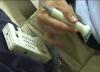
-
And also Audioguru, we will soon be going to the hospital for another checkup, and I'm going to record the sound from their electronic stethoscope :D, I'll post the sound file to night :).
-
Thanks Audioguru, that's exactly what I want to be able to do :), have as much control as possible to experiment with, while actually using the device.
Now I need to be able to do one more thing ;D, before I make these changes.
Can I replace R4 with a variable resistor, will doing this allow me to adjust its gain, the reason why I want to do this is because the way that I have made the stethoscope head.
I'll post more sound files as I progress 8). -
Hi audioguru,
These changes are giving very good results :D, I can hear heartbeat sounds very clearly with increased volume without distortion, I changed C2 to 0.47uF as you suggested and for C3 and C4 I used to 3.3uF, unfortunately I don't have much in the way of MKT capacitors of many different values to try, but come Thursday I shall get a few to try.
We tried listening for the babies heartbeat or four at least the sound of the blood rushing through the placenta, which sounds much like a heartbeat, which was what we heard when they used the electronic stethoscope at the hospital, but we could not hear any think.
I'm beginning to think that this project will not be able to do what I want it to do, but still it has been a very successful project performing the way it was meant to, and will be very useful 8).
Audioguru, this might be a completely stupid idea ::), but what would be the results of adding an extra 2 Mike's in parallel, then replicating every think from C2 to just before R11, so basically you would have three separate parallel TL072 stages feeding U5, would this give increase sensitivity and allow for a combination of filtering, basically allow for more flexibility of what sound you want and don't want and the amount of that sound to be allowed through to the final stage ???. -
Hi audioguru,
HAY if I can't get it to work well as a stethoscope, it sure does make a great AM radio :D ;D.
I connected one leg of a 0.1uF ceramic disc capacitor to pin 3 of U5, and the other leg touching my soldering iron, then I adjusted the volume control to tune into 1332AM 8). The capacitor was heating up a little but I had to keep it their, because there was a heated discussion about Dr Jayant Patel, who was the head surgeon here in Bundaberg and has fled the country because he was illegally performing surgery, including surgery on my partner Paula :o >:(. He was working here illegally using forged documents because he had been struck off the medical register in America. This guy is bad news, he is responsible for many deaths and botched surgerys :'(.
O I've gotten off track here a bit. I'm still trying yet more different stethoscope heads hoping to make a difference, as well as different microphones from my junk box. I tried connecting it to my stereo and I was able to turn the volume control up to nearly half, without any distraughtion or crackling noises, then I increased the volume using the stereo volume control, "WoW" it was loud and those little subwoofers were fairly thumping ;D. Even when I turn the stereo volume control write-down low there was very little noise but the speakers were still moving quite a bit.
Well my main goal with this project is to be able to here my unborn Childs heartbeat, so it doesn't really matter what it sounds like, as long as you can be certain that it is actually the heartbeat of the baby that you can here ;).
Hang on hold the phone, actually I don't think it is even the heartbeat that we were hearing at the hospital, I'm pretty certain it was the blood rushing through the heart that we could here, so would it be just a matter of isolating that frequency ??? -
Hi, audioguru, Alun
Sorry Audioguru for sending you on a wild goose chase :(, it seems as though my electronic stethoscope is working the way it should, and it is I that doesn't understand that it is :-[.
The electronic stethoscope that they used at the hospital sounded much different, I think that the sound that we were hearing, was a higher frequency representation of the actual heartbeat, so basically it worked the same way as this project filtering out all the sounds except for heartbeat sounds, but then modified the heartbeat sounds so that it could be clearly played at high volume on a small speaker.
So what I would like to try to do is take the signal from pin 7of UB1 then modify the signal to a higher frequency or in a way so that it can be fedback to be amplified and played at high volume on a speaker without distortion,
I guess the add-on circuit would work in a similar way as a voice changer?, if you were to say hello in a deep voice into it, it would come out the other end, clearly as (hello) but sounding like a chipmunk.
Now the big question is how do I go about achieving this ;D, how do I take a low frequency sound and turn it into a higher frequency sound ???.
Alun, that's a good idea I'll have to try that :D. -
Hi Audioguru :),
I've attached a sound file of exactly what I am hearing while listening to my heartbeat, while adjusting the volume control from minimum to maximum 8). As I adjust the volume control from its minimum I can just make out but barely hear my heartbeat it is very vary faint, with no distortion crackling or friction noises, if I adjust the volume control any more than about less than quarter, the distortion and crackling cuts in :(. I've tried using large plastic jar lids and metal lids of all different shapes and sizes with the same results, the stethoscope head I used for the recording is a very small metal jar lid with a small hole drilled in to it, to pass through the shielded cable, then I used a thick amount of hot glue to secure the Mike to the inside of the lid, then I coded the entire lid with a thick layer of hot glue including the rim that would come in contact with my skin, then came the fun part ;D ;D, I smeared some olive oil on my chest and still it didn't make any difference ???. -
Hi, audioguru and Thanks for your help,
(1) DC voltage at the microphone (4.80V)
(2) DC voltage at pin 7 of U1B ( 03.9mV )
(3) the DC voltage at pin 5 of U5 with the volume control turned down (4.19V) and with volume control turned fully on, it continuously changes between about (4.07V) and (4.22V)
I made the changes you suggested and it improved maybe a little.
The crackling only happens when I hold the stethoscope head to my skin, and when I hold the stethoscope head in the air I can hear the sound of the TV in the background, and the strength of the sound does rise and fall with the volume control. I did use 10V caps for C6 and C7 could this have cause any problems? I was at first convinced that it was the stethoscope head I was using, so I did try several different ones with no improvement :-\. -
Thanks for your reply audioguru :),
Yes, I did use a ceramic disc cap for C5. I had an idea that track placement would be important for this project, that's why I used the PCB pattern that a member posted, as I had no idea on correct track placement to design my own PCB, maybe I should give it a go, I will have to start by redrawing the schematics as I find it difficult to follow the way it is drawn, then I will need to post it for inspection to be sure I got it right, before having a go at designing a PCB, Mr Audioguru Buddy old Powell ;D, can you inspect my redrawn schematics once it is done and then the many attempts that I'm likely to make, at designing a decent PCB for this project ???.
Can you tell me which track placement are important, as I said I have no idea but I'm willing to have a go :), I'm sure others would appreciate a PCB for this project :).
This is the first time my partner has taken an interest in one of my electronic projects, she spent ages with it trying to hear our unborn child's heartbeat, even though it was barely working ;D. At our last checkup at the hospital they used a small handheld electronic stethoscope to listen to the babies heartbeat, it was just amazing to hear our babies heartbeat and that was what made me keen on making my own electronic stethoscope :D.
This will be our second child, our first is nine now our daughter, and it really is no less exciting then the first 8).
My partner had some very serious medical problems, not long after our daughter was born, as a result we didn't believe it possible to have another baby and in fact it is somewhat risky, for both mother and child and the medication that my partner must take ads to the risk :(, I think it would be very reassuring to be able to hear our babies heartbeat throughout the pregnancy :) :). -
Hi,
I've completed this project, electronic Stethoscope 2 :). Either I'm expecting too much from this project :(, or more than likely I've made an error some where :-\.
I can hear a "very vary" faint but clear heartbeat, when I adjust the 10K LOG potentiometer to around its minimum, say less than a quarter of its wipe,any more than that and I get crackling coming through the headphones, also when I first applied power I heard nothing coming through the headphones until I adjusted the potentiometer to about half and then I heard motor boating through the headphones, I applied power again about an hour later and this time it worked. I have experimented with different stethoscope heads and mikes, with very little improvement :(.
I use this PCB that someone posted and found that R8 and R7 were incorrect and needed to be swaped around, also I discovered that the positive and negative terminal connections are a dead short, so I connected them to negative of C8 and positive of C7, of course not before I flattened two 9V batteries ::) ;D, hopefully I haven't damaged one of the ICs, could this be why it's not working as well as I expected ???.
Now that I'm low on 9V batteries ;D, how do I power this project from my power supply, can I use two 9V regulators, how do I configure them ???.
-
Hi, MEHTAB AHMED :D
A lot of my work on this project is in the form of drawings, reactor chamber, high and low pressure chambers, filtering system, hi pressure pumps etc.
Are you wanting to take on this project? ;) -
Nice work Sasi 8), and all those pic's showing exactly how to make it :D, now anyone wanting to contact aliens can build your groundplane antenna ;D ;D.


Powering FM transmitter via USB?
in Electronic Projects Design/Ideas
Posted
Thanks for your help Audioguru :), I should be able to sort something out, I would prefer to try to use a voltage regulator if I can, and include a bridge rectifier which will be bypassed when powered from the USB, that way it could be powered by many different power sources such as my car. I have quite a few recycled adjustable voltage regulators so maybe one of them will be nice and work reliable on this low voltage.
Hi GreekPIC :), yes I did think of that first up, but then I realised why do that when I can power the transmitter directly from the USB, I'm killing two birds with one stone ;D, because at the moment the transmitter is power via batteries, so now I don't have to worry about using a transformer to power the transmitter.